


PN25

BURKERT 20022289 (Type 2000 CLASSIC) is a pneumatically operated 2/2-way angle seat valve with DN 15 ASME BPE clamp connection, PA actuator size 50 (D), normally closed function, and PTFE seat seal rated to 16 bar.
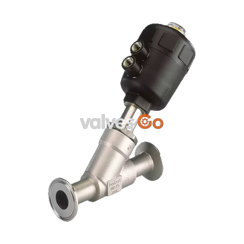
BURKERT 20022289 (Type 2000 CLASSIC) is an externally piloted 2/2-way pneumatic angle seat valve designed for shut-off control of liquids, gases, and steam in hygienic and industrial process applications. The valve incorporates a cast CF3M stainless steel body with ASME BPE clamp ends (DN 15, 1/2" tube specification, 25.0 mm clamp outer diameter) and a size 50 (D) polyamide (PA) pneumatic piston actuator. Configured in Control Function A (normally closed, NC), the valve closes against the medium flow by internal spring force and opens when pilot air between 4.1 bar and 10 bar is applied to the lower pilot air port.
Flow enters underneath the valve seat, utilizing fluid pressure to assist opening while preventing hydraulic water hammer in liquid pipework. Tight shut-off is ensured across a 0 to 16 bar operating pressure range by a durable PTFE seat seal and a self-adjusting PTFE V-ring packing gland with spring compensation. Certified to DIN EN 12266-1 Leakage Rate A and compliant with PN 25 / Class 150 pressure boundaries, article 20022289 is CIP and SIP cleanable, rated for medium temperatures from -10 °C to +185 °C, and supplied with an EN 10204 3.1 inspection certificate.
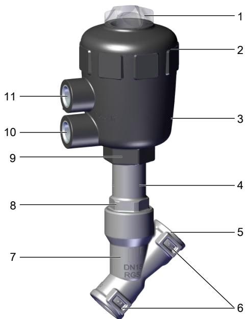
BURKERT 20022289 consists of a pneumatic piston actuator and a flow-optimized 2/2-way angle seat valve body. The actuator housing is molded from durable polyamide (PA) and features an integrated optical position indicator visible through a clear polycarbonate cover.
| Item | Description | Function |
|---|---|---|
| 1 | Transparent cover with position indicator | Provides visual optical indication of valve open/closed position |
| 2 | Actuator cover | Encloses the preloaded actuator spring package |
| 3 | Actuator housing (Polyamide PA) | Houses the pneumatic piston and return spring |
| 4 | Relief bore (overflow leak port) | Enables visual leak detection if stem packing gland requires service |
| 5 | Pipeline connection | ASME BPE clamp ferrule for sanitary pipe coupling |
| 6 | Flow direction arrow | Cast body marking indicating flow under the seat |
| 7 | Valve body (CF3M / 316L) | High-flow Y-pattern angle seat fluid chamber |
| 8 | Body neck connection with spanner flats | Threaded mechanical interface between body and actuator |
| 10 | Lower pilot air connection (G 1/4) | Air inlet for opening stroke in Control Function A |
| 11 | Upper pilot air connection (G 1/4) | Vent/exhaust port in single-acting Control Function A |
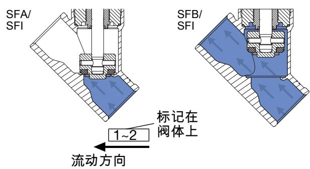
In Control Function A (SFA / CFA), the valve is held in the closed position by an internal stainless steel spring (1.4310) when no pilot pressure is present. The closing force is transmitted through a stainless steel spindle (1.4401 / 1.4404) directly to the CF3M swivel plate fitted with a precision PTFE seat seal.
Flow direction below the seat is specified for liquids, steam, and gases. Because media pressure acts on the underside of the swivel plate, line pressure assists in lifting the valve disc during opening. Closing against the oncoming flow avoids line shock and water hammer. Stem sealing is accomplished by a self-adjusting packing gland comprising filled PTFE V-rings energized by a stainless steel compensation spring, maintaining long-term sealing without manual maintenance.
| Parameter | Specification | Source Standard / Condition |
|---|---|---|
| Article Number | 20022289 | Burkert Master Catalog |
| Model Family | Type 2000 CLASSIC | 2/2-way angle seat valve |
| Nominal Diameter | DN 15 (NPS 1/2") | Seat orifice diameter: 15 mm |
| Port Connection Type | Clamp connection | ASME BPE / DIN 11866 series C |
| Clamp Flange Outer Diameter | 25.0 mm (0.984") | ASME BPE clamp size |
| Tube Dimensions | OD 12.7 mm x ID 9.4 mm | Wall thickness: 1.65 mm (0.065") |
| Control Function | Function A (NC) | Normally closed by spring force |
| Flow Direction | Below valve seat | Closes against flow, flow to open |
| Water Flow Coefficient Kv | 1.6 m³/h | +20 °C water, 1 bar Δp, free discharge |
| Operating Pressure Range | 0 to 16 bar(g) | SFA with PTFE seal, actuator 50 (D) |
| Nominal Pressure Rating | PN 25 / Class 150 | DIN EN 1333 / DIN EN 1759 |
| Pilot Pressure Range | 4.1 to 10 bar(g) | Single-acting Control Function A |
| Pilot Air Port | G 1/4 internal thread | 360° stepless rotatable connection |
| Control Medium | Instrument air, neutral gases | Filtered, non-lubricated or lubricated |
| Medium Temperature | -10 °C to +185 °C | Continuous process fluid limit |
| Ambient Temperature | -10 °C to +60 °C | Derated to +40 °C at +185 °C medium |
| Seat Leakage Rate | Leakage Rate A | DIN EN 12266-1 (air test medium) |
| Valve Body Material | Stainless steel CF3M | Precision cast 316L equivalent |
| Actuator Material | Polyamide (PA) | Size 50 (D), housing OD 64 mm |
| Seat Seal Material | PTFE | Polytetrafluoroethylene |
| Protection Rating | IP67 / NEMA 4X | EN 60529 / IEC 60529 |
| Sound Pressure Level | < 70 dB(A) | Operating noise limit |
| Fluid Viscosity | Max. 600 mm²/s | Dynamic process media |
| Cleanability | CIP and SIP capable | Steam-in-place and clean-in-place |
| Inspection Certificate | EN 10204 3.1 enclosed | Manufacturer material and test report |
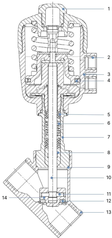
| Item No. | Component | Material Specification |
|---|---|---|
| 1 | Transparent cover | Polycarbonate (PC) |
| 2 | Pilot air connection inserts | Stainless steel 1.4305 |
| 3 | Actuator housing | Polyamide (PA) |
| 4 | Piston seal | NBR |
| 5 | Packing gland | PTFE V-rings (filled) with spring compensation |
| 6 | Actuator spring | Stainless steel 1.4310 |
| 7 | Guide tube | Stainless steel CF8 / CF3M |
| 8 | Wiper ring | Solid PTFE |
| 9 | Body seal | Graphite (PTFE optional) |
| 10 | Valve spindle | Stainless steel 1.4401 / 1.4404 (316 / 316L) |
| 11 | Retention pin | Stainless steel 1.4401 / 1.4404 |
| 12 | Valve seat seal | PTFE (virgin polytetrafluoroethylene) |
| 13 | Valve body | Stainless steel CF3M (cast 316L) |
| 14 | Swivel plate (seat disc) | Stainless steel CF3M / 1.4404 / 1.4401 |
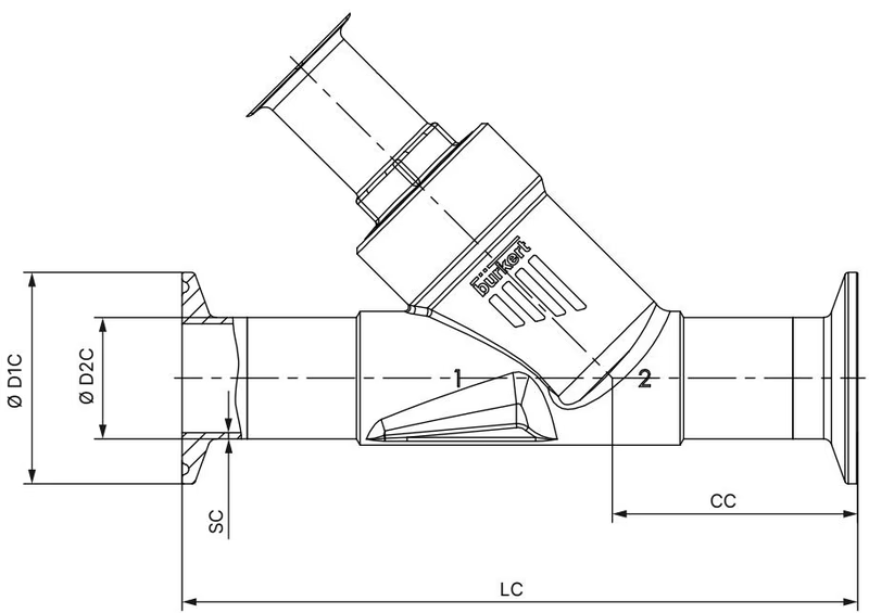
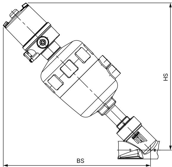
| Dimension Parameter | Value (mm) | Description |
|---|---|---|
| DN / NPS | DN 15 / NPS 1/2" | Nominal process line size |
| Face-to-face length LC | 130 mm | Total body length between clamp ferrule faces |
| Center-to-port length CC | 49.0 mm | Centerline of stem to inlet clamp face |
| Clamp outer diameter ∅ D1 C | 25.0 mm | Ferrule collar diameter (ASME BPE 1/2") |
| Tube outer diameter ∅ D2 C | 12.7 mm | Tube outer diameter |
| Tube wall thickness SC | 1.65 mm | Tube wall thickness (0.065") |
| Tube inner diameter | 9.4 mm | Calculated process bore (12.7 mm - 2 × 1.65 mm) |
| Actuator size | 50 (D) | Piston actuator designation |
| Actuator outer diameter ∅ A | 64 mm | Actuator housing diameter |
| Actuator height B / H | 145 mm | Centerline of body to top of actuator cap |
| Pilot port height K / M | 129 mm | Centerline of body to pilot air port center |
| Disassembly clearance BS / HS | 216 mm | Vertical clearance required for actuator removal |
| Pilot air connection P | G 1/4 | Internal thread for pneumatic hose fitting |
| Body tightening torque | 45 Nm (+10/-5 Nm) | Spanner flat tightening torque to body neck |
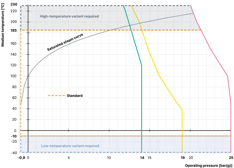
Operating pressure limits are governed by the mechanical ratings of the CF3M valve body and the thermal limits of the PTFE seat seal according to DIN EN 12516-1 PN 25 and ASME B16.34 Class 150:
| Medium Temperature (°C) | DIN EN 12516-1 PN 25 Limit (bar) | ASME B16.34 Class 150 Limit (bar) | 20022289 Maximum Operating Pressure (bar) |
|---|---|---|---|
| -10 to +38 °C | 25.0 | 19.0 | 16.0 |
| +50 °C | 25.0 | 18.4 | 16.0 |
| +100 °C | 24.5 | 16.2 | 16.0 |
| +150 °C | 22.4 | 14.8 | 14.8 |
| +185 °C | 20.9 | 14.0 | 14.0 |
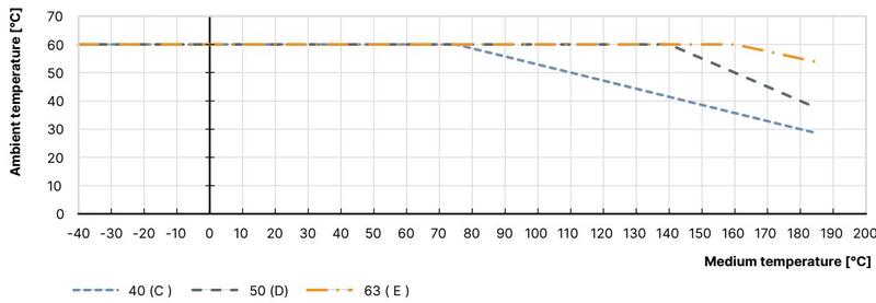
For polyamide (PA) actuators in size 50 (D), process heat conducted through the spindle into the actuator assembly requires ambient temperature derating. While the valve operates up to +60 °C ambient at low-to-medium fluid temperatures, process fluid at +185 °C restricts maximum permissible ambient temperature to +40 °C to prevent actuator overheating.
Operating Limits Caution
Operating pressures must remain below the saturation curve of steam to avoid cavitation and fluid flashes. If process temperature reaches +185 °C, ensure ambient temperature around the actuator does not exceed +40 °C.
Prior to installing BURKERT 20022289, flush the piping thoroughly to eliminate swarf, welding slag, and particulate contamination. Ensure connecting sanitary clamp gaskets and pipe ends are aligned without mechanical strain.
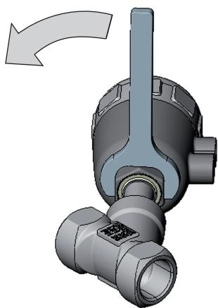
The control air connection can be aligned steplessly through 360° to accommodate tight piping layouts:
Actuator Rotation Precaution
Rotate the actuator only in the direction indicated on the housing. Turning in the opposite direction risks loosening the body-to-actuator connection, causing external leakage.
Prior to pressurizing process lines, test actuator switching by cycling pilot air pressure. Verify rapid stroke response via the transparent visual position indicator.
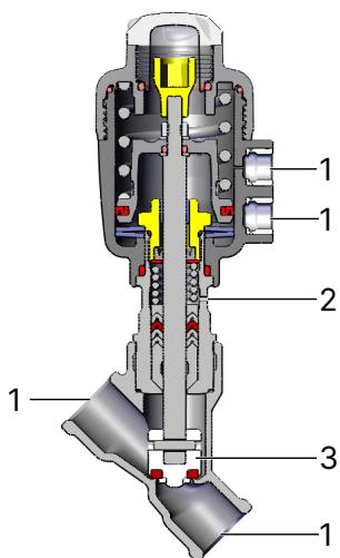
| Inspection Point | Observation | Corrective Action |
|---|---|---|
| Media Clamp Connection (1) | Fluid seepage at clamp ferrule joint | Re-seat gasket or replace sanitary clamp seal |
| Relief Bore / Overflow Port (2) | Moisture or media discharge at weep hole | Spindle packing gland worn: replace packing seal kit |
| Seat Disc / Swivel Plate (3) | Internal leakage past closed seat | PTFE seal worn or fouled: clear debris or replace seat disc |
| Body Neck Joint | Fluid leakage at body-actuator interface | Check graphite gasket, re-torque neck joint to 45 Nm |
| Symptom | Probable Cause | Remedial Action |
|---|---|---|
| Actuator does not switch | Pilot air connected to wrong port | Connect pilot supply to lower port (10) for Control Function A |
| Pilot pressure below 4.1 bar | Increase pilot air supply pressure to 4.1–10 bar | |
| Media pressure exceeds 16 bar | Regulate process fluid pressure within 0–16 bar range | |
| Reversed process flow direction | Verify line flow matches cast body arrow (below seat) | |
| Valve seat does not seal | Debris trapped between seat and disc | Flush line; install upstream strainer (mesh < 1 mm) |
| PTFE seat seal worn or damaged | Replace valve swivel plate assembly | |
| Leakage at relief bore | Spindle V-ring packing gland worn | Install replacement packing gland set with assembly tool |
BURKERT 20022289 can be accessorized with direct-mount automation units to support discrete process automation:
Explore similar products in our catalog



