


PN25

Burkert 20026190 (Type 2100) is a pneumatically operated 2/2-way angle seat valve with DN50 ASME BPE clamp ends, normally closed NC function, flow above seat, and PTFE seal.
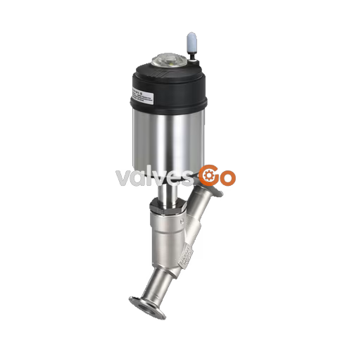
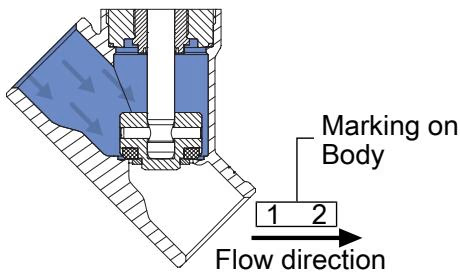
BURKERT 20026190 (Type 2100) is a pneumatically operated 2/2-way angle seat valve designed for decentralized process automation. Built with an investment cast stainless steel CF3M valve body and a PPS/stainless steel 1.4561 piston actuator, this configuration incorporates DN50 (NPS 2") ASME BPE clamp process connections, a 50 mm seat orifice diameter, an installation length of 230 mm, and a water flow coefficient Kv of 49 m³/h. The valve utilizes Control Function A (normally closed, closed by spring force in the unpressurized rest position) and is set up with flow direction above the seat (flow-to-close) for shutting off compressible media including steam, neutral gases, and industrial vapours.
Operating capabilities span vacuum conditions down to -0.9 bar(g) and positive operating pressures up to 12.0 bar(g), within a fluid temperature span of -10 °C to +185 °C. The valve assembly complies with EC Regulation 1935/2004 and FDA food contact regulations, ships with an EN 10204 3.1 inspection certificate, and is fully CIP/SIP capable. Pilot control is routed through an external 6 mm (1/4") push-in pneumatic connector, requiring a control pressure between 2.7 bar(g) and 7.0 bar(g) into the Ø 70 mm (Size M) actuator.

Operational Safety Restriction: Flow Above Seat Prohibited for Liquids
Risk of severe personal injury and equipment rupture caused by water hammer when fluid flows above the seat. In liquid service, sudden valve closure induces hydraulic pressure shockwaves that can burst pipes and the valve body. Bürkert Type 2100 valves configured with flow direction above the seat must never be used with liquid media. Use this valve only with steam, neutral gases, and gaseous media.
Operating Pressure and Pilot Limits
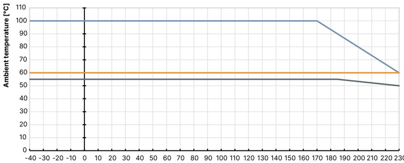
Operating pressure must not exceed 12.0 bar(g) for the DN50 seat with Ø 70 mm actuator in flow-above-seat configuration. Pilot pressure must be set within 2.7 to 7.0 bar(g). Operating outside the specified medium temperature range of -10 °C to +185 °C or ambient temperature range of -10 °C to +60 °C (governed by the push-in pneumatic fitting) will degrade seals and compromise valve performance.
Burkert 20026190 functions as a single-acting on/off valve. In the rest position without pilot air, the internal stainless steel 1.4310 spring pack exerts continuous closing force through the spindle to push the swivel plate onto the valve seat. Because the process fluid enters above the swivel plate, line pressure actively assists the spring in pressing the PTFE seal firmly against the seat orifice. This flow-to-close design enhances seat tightness (Leakage rate A in accordance with DIN EN 12266-1) against compressible steam and gases.
Opening the valve requires supplying compressed air to pilot air port 1. When pilot pressure exceeds the counteracting spring force and process line pressure, the actuator piston travels upward, lifting the swivel plate away from the seat. Evacuating pilot air port 1 vents the lower piston chamber, allowing the spring force and medium pressure to return the valve to the closed position.
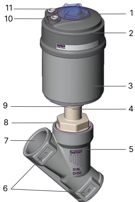
| Position | Component Name | Function / Description |
|---|---|---|
| 1 | Transparent cap | Visual position indicator display housing |
| 2 | Actuator cover | Polyphenylene sulphide (PPS) top casing |
| 3 | Actuator housing | Stainless steel 1.4561 (316Ti) cylinder |
| 4 | Relief bore | Atmospheric leakage monitoring port for packing gland |
| 5 | Valve body | Stainless steel CF3M investment cast angle seat body |
| 6 | Flow direction marking | Directional arrow cast into the body wall |
| 7 | Port connection | ASME BPE hygienic clamp connection |
| 8 | Body connection | Hexagonal interface connecting body and bonnet |
| 9 | Actuator connection | Hexagonal drive connection nut |
| 10 | Pilot air port 1 | Pneumatic control air inlet (valve opening chamber) |
| 11 | Pilot air port 2 | Exhaust / spring chamber vent (fitted with silencer) |
Long-term spindle sealing is maintained by a self-adjusting PTFE V-ring packing gland loaded by spring compensation. Spindle guidance is provided by a virgin PEEK bush to prevent galling under high-cycle industrial actuation. All wetted components meet sanitary design guidelines, and lubricants applied to the packing gland and actuator internals are certified NSF H1.
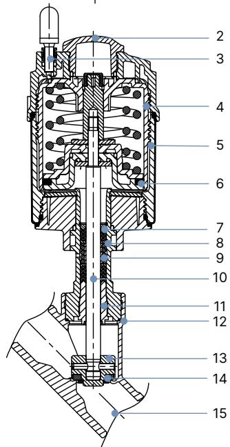
| Item | Component | Material |
|---|---|---|
| 1 | Ground terminal | Stainless steel 1.4301 / 1.4305 (supplied with ATEX variants) |
| 2 | Optical position indicator | Polysulfone (PSU) |
| 3 | Pilot air ports | Polypropylene (PP) push-in fitting (external Ø 6 mm / 1/4") |
| 4 | Actuator cover | Polyphenylene sulphide (PPS) |
| 5 | Actuator casing | Stainless steel 1.4561 (316Ti) |
| 6 | Piston seal | Fluoroelastomer (FKM) |
| 7 | Spring | Stainless steel 1.4310 |
| 8 | Pipe | Stainless steel 1.4401 (316) / 1.4404 (316L) |
| 9 | Packing gland | Filled PTFE V-rings with spring compensation |
| 10 | Spindle | Stainless steel 1.4401 (316) / 1.4404 (316L) |
| 11 | Spindle guide | Polyether ether ketone (PEEK) |
| 12 | Body seal | Graphite (standard) / PTFE (option) |
| 13 | Swivel plate | Stainless steel 1.4401 (316) / 1.4404 (316L) |
| 14 | Seat seal | Polytetrafluoroethylene (PTFE) |
| 15 | Valve body | Stainless steel CF3M (cast 316L equivalent) |
Maximum working pressure for article 20026190 is 12.0 bar(g). The structural valve body pressure integrity corresponds to PN 25 per DIN EN 1333 and Class 150 per DIN EN 1759 / ASME B16.34. Permissible operating pressure derates at elevated process temperatures according to pressure vessel directives.
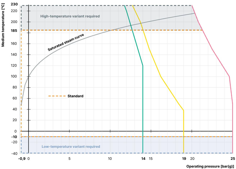
| Medium Temperature [°C] | Maximum Permissible Operating Pressure [bar(g)] |
|---|---|
| -10 to +50 | 25.0 |
| +100 | 24.5 |
| +150 | 22.4 |
| +200 | 20.3 |
| +230 | 19.0 |
| Medium Temperature [°C] | Maximum Permissible Operating Pressure [bar(g)] |
|---|---|
| -29 to +38 | 19.0 |
| +50 | 18.4 |
| +100 | 16.2 |
| +150 | 14.8 |
| +200 | 13.7 |
| +230 | 12.7 |
Vacuum Variant Specification
Article 20026190 is constructed without an external atmospheric relief bore on the packing gland zone. This sealed execution enables leak-tight process operation under vacuum conditions down to -0.9 bar(g) without ingress of ambient air.
The valve body has hygienic clamp ends certified to ASME BPE (DIN 11866 Series C pipe dimensions). Clamp connections provide tool-free sanitary installation using tri-clamp gaskets and clamp bands.
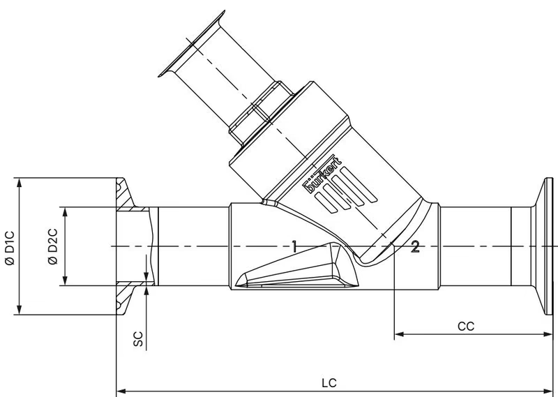
| Nominal Port Size (NPS) | Nominal Diameter (DN) | Face-to-Face Length LC [mm] | Centerline Height CC [mm] | Clamp Flange Outer Ø D1 C [mm] | Pipe Outer Ø D2 C [mm] | Pipe Wall Thickness SC [mm] |
|---|---|---|---|---|---|---|
| 1/2" | DN 15 | 130 | 49.0 | 25.0 | 12.70 | 1.65 |
| 3/4" | DN 20 | 150 | 56.5 | 25.0 | 19.05 | 1.65 |
| 1" | DN 25 | 160 | 58.0 | 50.5 | 25.40 | 1.65 |
| 1 1/2" | DN 40 | 200 | 69.0 | 50.5 | 38.10 | 1.65 |
| 2" (Article 20026190) | DN 50 | 230 | 77.5 | 64.0 | 50.80 | 1.65 |
| Actuator Size | Actuator Outer Ø A [mm] | Dimension B [mm] | Dimension H [mm] | Dimension K/M [mm] |
|---|---|---|---|---|
| 70 mm (Size M) - 20026190 | 91 | 223 | 219 | 196 |
| 90 mm (Size N) | 120 | 262 | 261 | 236 |
| 130 mm (Size P) | 159 | 312 | 312 | 273 |
Note: Dimensions B, H, K, and M represent maximum dimensions and may be up to 6 mm less depending on process connection orifice size and manufacturing tolerances.
| Actuator Size | Body Size | Overall Height B/H with Type 8690 / Type 8697 [mm] | Overall Height B/H with Type 8691 / Type 8695 [mm] |
|---|---|---|---|
| 70 mm (Size M) - 20026190 | DN 50 | 274 | 297 |
| 90 mm (Size N) | DN 50 | 313 | 337 |
| 130 mm (Size P) | DN 50 | 351 | 374 |
Pilot air supply lines connect to the actuator via integrated push-in fittings accommodating 6 mm (or 1/4") outer diameter flexible pneumatic tubing. Port 1 is the control air inlet for opening the valve. Port 2 vents the spring chamber during opening strokes and is supplied with a screw-in porous bronze silencer to reduce exhaust air discharge noise below 70 dB(A). In corrosive industrial environments, Port 2 should be piped into a clean neutral atmosphere.
The actuator body rotates through 360° to adjust pneumatic ports toward incoming air tubing or automation cabling.
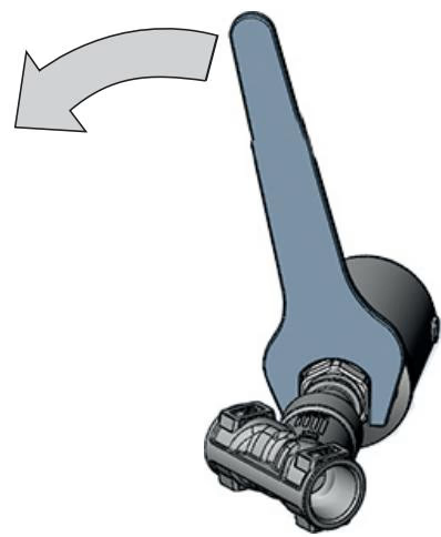
Mandatory Actuator Rotation Procedure
When rotating the actuator to adjust pilot air port alignment, apply open-end wrenches simultaneously to the actuator drive hexagon nut and the body connection hexagon nut. Rotate the actuator only in the direction shown on the actuator casting arrow. Rotating in the opposite direction can unscrew the body connection, resulting in medium leakage and seal destruction during process pressurization.
Burkert Type 2100 forms part of the modular ELEMENT valve architecture. The actuator interface permits direct coupling of automation heads without external air tubing:
Ensure process pipework is aligned axially and cleared of debris prior to clamping the valve body. Clamp connection ferrule gaskets must be positioned squarely to avoid turbulent flow disturbances.
| Nominal Diameter (DN) | Applicable Actuator Sizes | Tightening Torque [Nm] | Tolerance [Nm] |
|---|---|---|---|
| DN 15 | 40 (C), 50 (D), 63 (E) | 45 | +10 / -5 |
| DN 20 | 40 (C), 50 (D), 63 (E), 80 (F) | 50 | +10 / -5 |
| DN 25 | 50 (D), 63 (E), 80 (F) | 60 | +10 / -5 |
| DN 32 | 63 (E), 80 (F), 100 (G) | 65 | +10 / -5 |
| DN 40 | 63 (E), 80 (F), 100 (G), 125 (H) | 65 | +10 / -5 |
| DN 50 (Article 20026190) | 63 (E), 70 (M), 80 (F), 90 (N), 100 (G), 125 (H) | 70 | +10 / -5 |
| DN 65 | 80 (F), 100 (G), 125 (H) | 70 | +10 / -5 |
| DN 65 | 175 (K), 225 (L) | 100 | +10 / -5 |
| DN 80 | 125 (H), 130 (P) | 120 | +10 / -5 |
| DN 100 | 125 (H), 175 (K), 225 (L) | 150 | +10 / -5 |
Actuator Removal and Reassembly Instruction
When unscrewing or reinstalling the actuator onto the stainless steel valve body, the valve must be in the fully open position. For Control Function A, apply 5.0 bar(g) compressed air to pilot air port 1 to retract the swivel plate. Removing or screwing down the actuator while the seat seal is resting against the body seat causes rotational friction that destroys the PTFE seal ring.
Perform periodic visual inspections on the three primary sealing zones illustrated below.
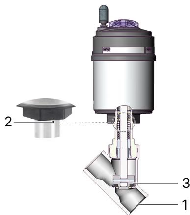
| Inspection Point | Observed Fault | Remedial Action |
|---|---|---|
| 1: Media connectors | Flange leakage at ASME BPE clamp ferrule | Replace clamp gasket and re-tighten clamp band |
| 2: Relief bore / packing zone | Fluid weeping from spindle gland area | Replace packing gland seal kit or actuator subassembly |
| 3: Swivel plate seat | Internal cross-seat leakage in closed position | Replace swivel plate assembly with fresh PTFE seal |
| Symptom | Probable Cause | Corrective Measure |
|---|---|---|
| Actuator fails to switch | Control air connected to incorrect port | Connect pilot supply line to Pilot Port 1 (CFA) |
| Pilot air pressure below 2.7 bar(g) | Increase control pressure to specified 2.7–7.0 bar(g) | |
| Operating line pressure exceeds 12.0 bar(g) | Reduce upstream system pressure within allowable limit | |
| Medium flow reversed | Verify flow enters above seat per directional body arrow | |
| Internal seat leakage | Debris trapped between PTFE seal and seat | Flush pipeline; install upstream particulate strainer |
| Worn or gouged PTFE seat seal ring | Install replacement swivel plate kit (Art. No. on inquiry) | |
| Operating pressure exceeds actuator spring rating | Adjust line pressure or pilot control parameters | |
| External leakage at relief bore | Spindle packing gland V-rings worn | Replace PTFE packing gland using socket wrench Art. 683221 |
| Actuator loose on valve body | Thermal cycling or vibration loosened threads | Re-torque body connection nut to 70 Nm (+10/-5 Nm) |
Explore similar products in our catalog



