PN25

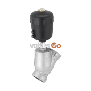
BURKERT 20062039 (Type 2101) pneumatic 2/2-way globe valve features a 316L stainless steel body, DN 100 ISO 4200 weld ends, PTFE seal, normally closed function, and KTW-BWGL drinking water approval.
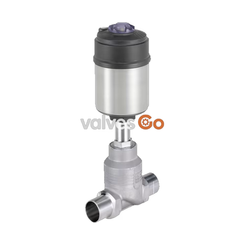
BURKERT 20062039 (Type 2101) is a pneumatically operated 2/2-way globe valve configured for demanding shut-off applications and decentralized automation. This specific configuration features a DN 100 (4") cast stainless steel 316L body with ISO 4200 weld ends, an integrated Ø 130 mm PPS piston actuator, and a PTFE seat seal. Operating under Control Function A (normally closed by spring force), the valve routes fluid flow below the valve seat, delivering a flow coefficient Kv of 165 m³/h and ensuring water-hammer-free shut-off across an operating pressure range of 0 to 6 bar(g). The wetted materials comply with the German Federal Environment Agency (UBA) KTW-BWGL assessment principles for drinking water applications up to +85 °C.
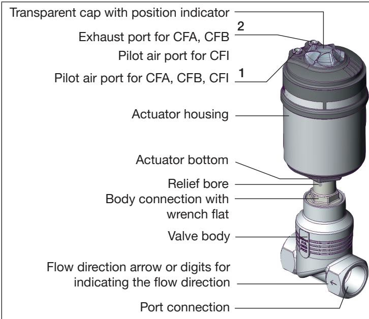
BURKERT 20062039 consists of a pneumatically driven piston actuator mounted on a two-way globe valve body. Force transmission occurs via a stainless steel spindle connected directly to the swivel plate. In the unpressurized rest position, internal compression springs press the swivel plate against the screwed-in valve seat, maintaining tight shut-off.

Medium flow enters below the seat. Under this configuration, the operating pressure acts against the closing direction, assisting opening when pilot air is supplied to pilot port 1. This prevents hydraulic shock in liquid media lines.
Risk of Pressure Surge with Flow Above Seat
Valves with medium flow above the seat must not be used for liquid media due to severe water hammer risk that can burst pipework and valve bodies. Article 20062039 is engineered exclusively for flow below the seat.
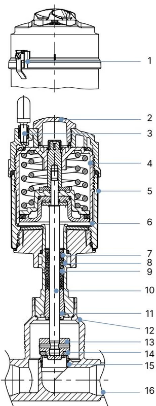
All lubricants utilized within the packing gland and pneumatic actuator are categorized according to NSF H1.
| Item | Component | Material |
|---|---|---|
| 1 | Ground terminal | Stainless steel 1.4301 / 1.4305 (ATEX variants) |
| 2 | Optical position indicator | Polysulfone (PSU) |
| 3 | Pilot air ports | Polypropylene (PP) push-in connector |
| 4 | Actuator cover | Polyphenylene sulphide (PPS) |
| 5 | Actuator casing | Stainless steel 1.4561 (316Ti) |
| 6 | Piston seal | FKM |
| 7 | Spring | Stainless steel 1.4310 |
| 8 | Tube / pipe | Stainless steel 1.4401 (316) / 1.4404 (316L) |
| 9 | Spindle packing | PTFE V-rings (filled), spring-compensated |
| 10 | Spindle | Stainless steel 1.4401 (316) / 1.4404 (316L) |
| 11 | Spindle guide | Stainless steel 1.4401 / 1.4404 (DN 80–DN 100) |
| 12 | Body seal | Graphite (PTFE optional) |
| 13 | Swivel plate | Stainless steel 1.4401 (316) / 1.4404 (316L) |
| 14 | Seat seal | PTFE |
| 15 | Valve seat with O-ring | Stainless steel 1.4571, EPDM |
| 16 | Valve body | Stainless steel 316L / CF3M |
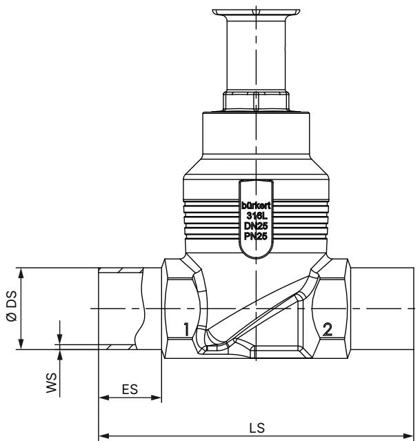
Article 20062039 is equipped with ISO 4200 weld ends for direct integration into industrial piping networks.
| Port Connection DN | Outer Pipe Ø DS [mm] | Wall Thickness WS [mm] | Length LS [mm] | Weld Insertion ES [mm] |
|---|---|---|---|---|
| DN 100 | 114.3 | 2.6 | 260 | 26 |
| Port Connection DN | Actuator Size Ø [mm] | Actuator Outer Ø A [mm] | Total Height H [mm] |
|---|---|---|---|
| DN 100 | 130 (P) | 159 | 475 |
For DN 100 with actuator size Ø 130 mm, the minimum pilot pressure required to overcome spring tension and open the valve is 5.6 bar(g). The maximum permissible pilot pressure for actuator size Ø 130 mm is 7.0 bar(g).
| Parameter | Specification |
|---|---|
| Operating pressure range | 0 to 6 bar(g) |
| Required pilot pressure | 5.6 to 7.0 bar(g) |
| Nominal pressure rating | PN 25 (DIN EN 1333), Class 150 (DIN EN 1759) |
| Flow coefficient Kv (water at +20 °C) | 165 m³/h |
| Maximum medium velocity limits (PED) | 10 bar maximum for compressible fluids Group 1 at DN 100 |
| Temperature rating (drinking water conformity PF39) | -10 °C to +85 °C |
| Ambient operating temperature | -10 °C to +100 °C |
| Protection class | IP65 / IP67 according to IEC 529 / EN 60529 |
Operating Pressure Derating
Nominal pressure ratings depend on the operating temperature. For stainless steel 316L bodies rated PN 25 under DIN EN 12516-1, maximum pressure derates from 25 bar (-10 °C to +50 °C) to 24.5 bar at +100 °C, 22.4 bar at +150 °C, and 20.3 bar at +200 °C.
Observe installation procedures to safeguard internal valve trims:
| Connection Size DN | Body Connection Tightening Torque [Nm] |
|---|---|
| DN 15 | 45 ± 3 |
| DN 20 | 50 ± 3 |
| DN 25 | 60 ± 3 |
| DN 32 / DN 40 | 65 ± 3 |
| DN 50 | 70 ± 3 |
| DN 65 | 100 ± 3 |
| DN 80 | 120 ± 5 |
| DN 100 | 150 ± 5 |
Rotating Actuator Alignment
The pneumatic pilot ports can be aligned across 360° to accommodate tight plant layouts. Apply 5 bar pilot pressure to port 1 to lift the swivel plate off the seat, attach an open-end wrench to the body connection, and rotate the actuator counterclockwise as viewed from below.
Connect the supply medium (neutral gases or air) to pilot air port 1 using 6/4 mm or 1/4" pneumatic tubing. In control function A, pressurizing port 1 opens the valve. A push-in silencer is supplied unattached to protect the spring chamber at exhaust port 2 against contamination. In aggressive atmospheres, connect exhaust port 2 to a neutral venting area.
Under intended operating conditions, the pneumatic actuator is maintenance-free. Regular visual inspections must include checking external line connections and observing the spindle relief bore on the intermediate tube for fluid leakage. Leakage at the relief bore indicates packing gland wear.
| Spare Part Assembly | Applicable Size | Order Number |
|---|---|---|
| Valve set (swivel plate, pin, PTFE seal, body seal) | DN 100 | 155 493 |
| Seal set for packing gland (PTFE chevron pack, spring, seal) | DN 80–DN 100 (Actuator Ø 130 mm) | 252 545 |
| VA spindle guide SP22 (spindle Ø 22 mm) | DN 80–DN 100 (Actuator Ø 130 mm) | 252 543 |
| Valve seat set (valve seat, EPDM O-ring, seal) | DN 100 | 262 210 |
| Assembly tool for valve seat replacement | DN 100 | 655 564 |
When replacing the screwed-in valve seat using assembly tool 655 564, grease the seat threads with Klüberpaste UH1 96-402 and tighten the DN 100 seat to 220 + 10 Nm.
BURKERT 20062039 is prepared for direct integration with ELEMENT series automation accessories to create the Type 8801-GC valve system:
Explore similar products in our catalog