


PN25

BURKERT 20062978 Type 2101 is a pneumatically operated 2/2-way DN40 globe valve with DIN EN 1092-1 PN25 flange connection, normally closed control function A, PTFE seal, and stainless steel 316L body.
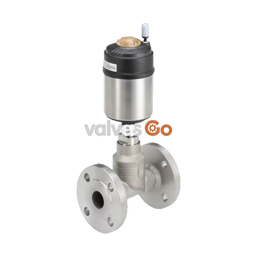
BURKERT 20062978 (Type 2101) is a pneumatically operated 2/2-way globe valve configured for decentralized process automation in sanitary, chemical, and industrial processing systems. Engineered as part of the ELEMENT architectural platform, this configuration features a nominal diameter of DN 40, flanged process connections according to DIN EN 1092-1 PN 25, control function A (normally closed by spring force), and media flow beneath the valve seat. The wetted assembly combines a 316L stainless steel cast valve body with a replaceable PTFE seat seal and self-adjusting PTFE V-ring spindle packing, certified compliant with Regulation (EC) No 1935/2004 and FDA CFR Title 21 food contact standards.

Equipped with a Ø 90 mm (Size N) polyphenylene sulphide (PPS) piston actuator, the unit achieves a flow coefficient Kv of 31 m³/h and controls media pressures up to 16 bar(g) with a minimum pneumatic pilot pressure of 5.0 bar(g). The valve is certified CIP (Clean-in-Place) and SIP (Steam-in-Place) capable, handling continuous operating medium temperatures from -10 °C to +185 °C.
| Technical Parameter | Specification Value |
|---|---|
| Valve Type | Type 2101 (ELEMENT series) |
| Article Number | 20062978 |
| Port Connection Type | Flange according to DIN EN 1092-1 PN 25 (FTF 1 per DIN EN 558-1) |
| Nominal Diameter | DN 40 (seat diameter 40 mm) |
| Control Function | Control function A (CF A, normally closed by spring force) |
| Flow Direction | Below seat (anti-water hammer) |
| Operating Pressure Range | 0 to 16 bar(g) |
| Pilot Pressure Range | 5.0 bar(g) min. to 10.0 bar(g) max. |
| Flow Factor Kv (Water) | 31 m³/h (measured at +20 °C, 1 bar Δp) |
| Medium Temperature Range | -10 °C to +185 °C |
| Ambient Temperature Range | -10 °C to +100 °C (derates to +55 °C when pilot valves are attached) |
| Maximum Medium Viscosity | Up to 600 mm²/s |
| Seat Leakage Class | Leakage rate A according to DIN EN 12266-1 |
| Valve Body Material | Stainless steel 316L / CF3M |
| Actuator Housing Material | Polyphenylene sulphide (PPS) with 1.4561 (316Ti) casing |
| Seat Seal Material | PTFE (Polytetrafluoroethylene) |
| Actuator Size | Ø 90 mm (Designation N) |
| Pilot Air Connection | Push-in connector external Ø 6 mm (ELEMENT interface) |
| Enclosure Rating | IP65 / IP67 according to IEC 529 / EN 60529 (NEMA 4X) |
| Hygienic Compliance | Regulation (EC) 1935/2004, FDA 21 CFR compliance declaration |
| Directives Compliance | Pressure Equipment Directive 2014/68/EU, Machinery Directive 2006/42/EC |
BURKERT Type 2101 utilizes a pneumatic piston actuator operating against a calibrated mechanical spring pack. Under Control Function A (normally closed), the internal spring pack acts downward on the actuator spindle and swivel plate, holding the PTFE valve disk tightly sealed against the screwed-in stainless steel valve seat.

Pilot air introduced through port 1 pressurizes the piston chamber beneath the actuator piston, overcoming the spring tension to lift the spindle and open the flow path. Flow enters beneath the seat and discharges through the lateral port. Because operating pressure acts on the underside of the swivel plate, line pressure assists valve opening, preventing pressure surges when cycling.
Water Hammer Restriction
Valves configured with flow direction above the seat must not be used for liquid media due to severe water hammer risk that can burst pipework. BURKERT 20062978 is manufactured exclusively for flow below the seat, making it suitable for liquids, saturated steam, and neutral gases.
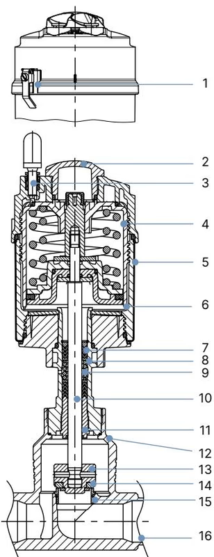
| Item No. | Component | Material Specification |
|---|---|---|
| 1 | Ground terminal | Stainless steel 1.4301 / 1.4305 (for ATEX variants) |
| 2 | Optical position indicator | Polysulfone (PSU) |
| 3 | Pilot air port | Polypropylene (PP) push-in fitting Ø 6 mm |
| 4 | Actuator cover | Polyphenylene sulphide (PPS) |
| 5 | Actuator casing | Stainless steel 1.4561 (316Ti) |
| 6 | Piston seal | FKM |
| 7 | Actuator springs | Stainless steel 1.4310 |
| 8 | Spindle tube / pipe | Stainless steel 1.4401 (316) / 1.4404 (316L) |
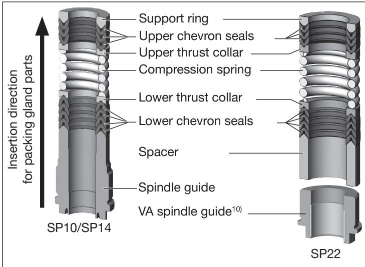
| 9 | Spindle packing gland | Filled PTFE V-rings, spring-compensated |
| 10 | Spindle (stem) | Stainless steel 1.4401 (316) / 1.4404 (316L) |
| 11 | Spindle guide | PEEK (for sizes DN 15 to DN 65) |
| 12 | Body seal | Graphite (PTFE optional) |
| 13 | Swivel plate (swing disc) | Stainless steel 1.4401 (316) / 1.4404 (316L) |
| 14 | Seat seal | PTFE (Polytetrafluoroethylene) |
| 15 | Valve seat with O-ring | Stainless steel 1.4571 with EPDM O-ring |
| 16 | Valve body | Stainless steel 316L / CF3M |
All internal lubricants applied to the packing gland and actuator are classified under NSF H1 for incidental food contact.
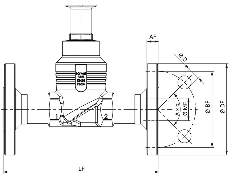
The process connections are welded-flange bodies complying with DIN EN 1092-1 PN 25 with face-to-face dimensions conforming to DIN EN 558-1 Series FTF 1. Actuator dimensions correspond to size Ø 90 mm (N).
| Dimension Designation | Value for DN 40 PN 25 |
|---|---|
| Flange outer diameter (Ø DF) | 150 mm |
| Face-to-face body length (LF) | 200 mm |
| Pitch circle diameter (Ø BF) | 110 mm |
| Flange thickness (AF) | 18 mm |
| Bolt hole diameter (Ø D) | 18 mm |
| Bolt hole pattern (A × α) | 4 × 90° |
| Seat orifice diameter (Ø MF) | 44.3 mm |
| Actuator outer diameter (Ø A) | 120 mm |
| Total assembled height (H) | 345 mm |
Actuator Alignment
The actuator housing can be rotated continuously by 360° relative to the body connection without dismantling the process connection, enabling orientation of the pilot air ports.
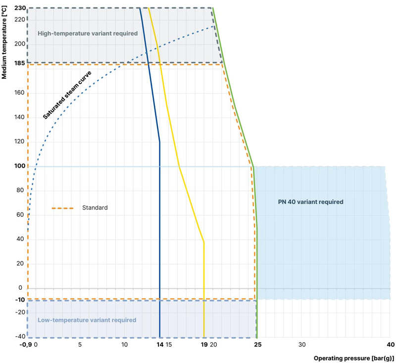
The maximum permissible working pressure is determined by the nominal actuator rating (16 bar for Ø 90 mm on DN 40) and material derating curves in accordance with DIN EN 12516-1.
| Medium Temperature (°C) | Maximum Permissible Pressure PN 25 (DIN EN 12516-1) | Applied Valve Limit (Article 20062978) |
|---|---|---|
| -10 °C to +50 °C | 25.0 bar | 16.0 bar |
| +100 °C | 24.5 bar | 16.0 bar |
| +150 °C | 22.4 bar | 16.0 bar |
| +185 °C | 21.0 bar | 16.0 bar |
| +200 °C | 20.3 bar | Exceeds PTFE seat seal limit (+185 °C) |
Pilot air supply must maintain a minimum of 5.0 bar(g) to overcome spring resistance and media line pressure up to 16 bar(g). The maximum permissible pilot pressure on the Ø 90 mm PPS actuator is 10.0 bar(g).
BURKERT 20062978 is designed for integration into the ELEMENT decentralized control network. It supports direct modular attachment of Burkert control heads and positioners without external pneumatic lines:
Internal pilot air passages channel exhaust and supply air directly through the actuator neck, venting the spring chamber with dry control air to prevent ambient moisture from entering the spring pack.
Installation may occur in any spatial orientation, though an upright actuator position is recommended. Pipeline lines must be cleared of weld slag and particulate matter prior to installation.
Maintenance Precautions
The pneumatic actuator contains a factory-compressed spring pack. Never unbolt or open the actuator casing. When unscrewing the actuator assembly from the valve body, apply 5 bar(g) of compressed air to pilot port 1 to lift the swivel plate off the valve seat, preventing seal shear.
Explore similar products in our catalog



