PN25

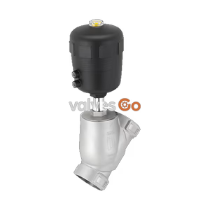
Burkert Type 2100 (SKU 20073155) pneumatically operated 2/2-way angle seat valve. Features stainless steel body, PTFE seal, weld end, DN20, and handles pressures up to 25 bar.
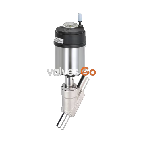
Burkert Type 2100 (SKU 20073155) pneumatically operated 2/2-way angle seat valve is specially optimised for decentralized process automation and fulfils the tough criteria in process environments. Its unique design allows easy integration of automation units in all expansion stages, from electrical/optical position feedback to pneumatic control and integrated fieldbus interface. Maximum service life and tightness are achieved by the proven self-adjusting v-seal packing gland. The highly integrated system of valve and automation unit is characterised by its compact and smooth design, integrated pilot air ducts, protection classes IP65/67, NEMA Type 4X, and high resistance to chemicals.

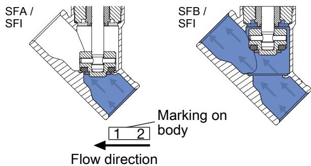
Only use flow direction below the seat for liquid media, gases, and vapours. As the medium is present under the swivel plate, the operating pressure contributes to the opening of the valve.
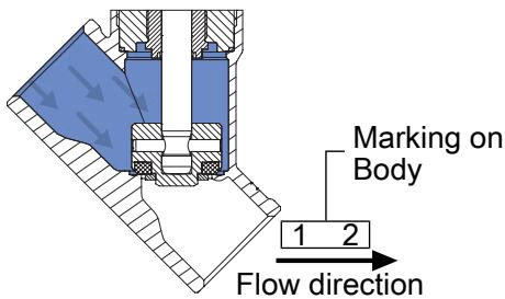
Only use flow direction above the seat for gases and vapours, and for valves with control function A (closed by spring force in rest position). As the medium is present above the swivel plate, the operating pressure contributes to the closing of the valve. The operating pressure also supports the sealing of the valve seat.
DANGER
Bursting lines and bursting device with flow direction above the seat In the case of liquid media, a pressure surge can lead to the bursting of lines and device. Do not use valves with flow direction above the seat for liquid media.
INFO
The lubricants for packing gland and actuator are classified according to NSF H1.
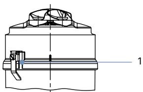
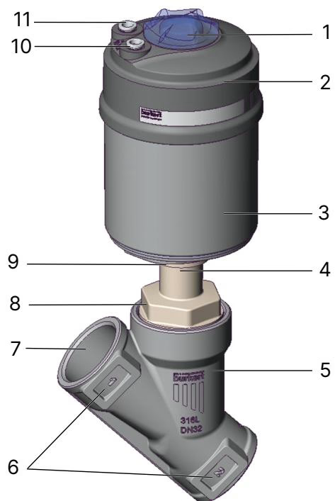
| No. | Element | Material |
|---|---|---|
| 1 | Ground terminal | Stainless steel 1.4301/1.4305 (only for ATEX variant) |
| 2 | Optical position indicator | Polysulfone PSU |
| 3 | Pilot air ports | Push-in connector PP (Standard) |
| 4 | Actuator cover | PPS |
| 5 | Actuator casing | Stainless steel 1.4561 (316Ti) |
| 6 | Piston seal | FKM |
| 7 | Spring | Stainless steel 1.4310 |
| 8 | Pipe | Stainless steel 1.4401 (316)/1.4404 (316L) |
| 9 | Packing gland | PTFE V-Rings (filled), with spring compensation |
| 10 | Spindle | Stainless steel 1.4401 (316)/1.4404 (316L) |
| 11 | Spindle guide | PEEK |
| 12 | Body seal | Graphite, PTFE (Option) |
| 13 | Swivel plate | Stainless steel 1.4401 (316)/1.4404 (316L) |
| 14 | Seat seal | PTFE, PEEK (Option) |
| 15 | Valve body | Stainless steel CF3M |
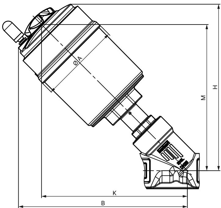
| Nominal diameter (DN) | Actuator size ∅ | ∅ A [mm] | B [mm] | H [mm] | K/M [mm] |
|---|---|---|---|---|---|
| 15 | 50 (D) | 64.5 | 166 | 163 | 147 |
| 15 | 70 (M) | 91 | 182 | 178 | 156 |
| 20 | 50 (D) | 64.5 | 174 | 171 | 155 |
| 20 | 70 (M) | 91 | 189 | 186 | 163 |
| 25 | 50 (D) | 64.5 | 175 | 173 | 156 |
| 25 | 70 (M) | 91 | 191 | 188 | 165 |
| 25 | 90 (N) | 120 | 229 | 228 | 203 |
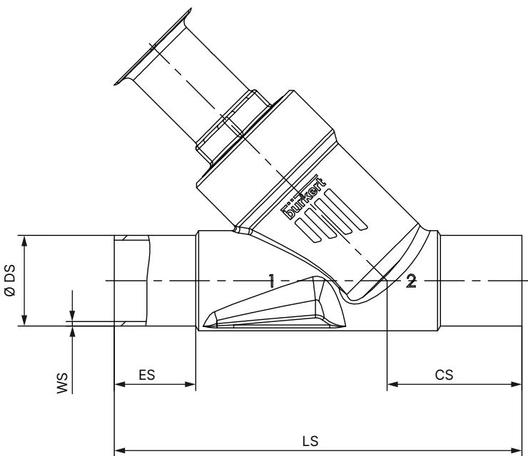
| Nominal diameter (DN) | DIN EN ISO 1127 / ISO 4200 / DIN 11866 series B (ES / CS / LS / ∅ DS / WS) | DIN 11850-2 / DIN 11866 series A (ES / CS / LS / ∅ DS / WS) |
|---|---|---|
| 15 | 19 / 34 / 100 / 21.3 / 1.6 | 19 / 34 / 100 / 19 / 1.5 |
| 20 | 20 / 39 / 115 / 26.9 / 1.6 | 20 / 39 / 115 / 23 / 1.5 |
| 25 | 26 / 43 / 130 / 33.7 / 2.0 | 26 / 43 / 130 / 29 / 1.5 |
In addition to the maximum operating pressures, the operating range of Bürkert process valves is limited by the nominal pressure according to the relevant standard.
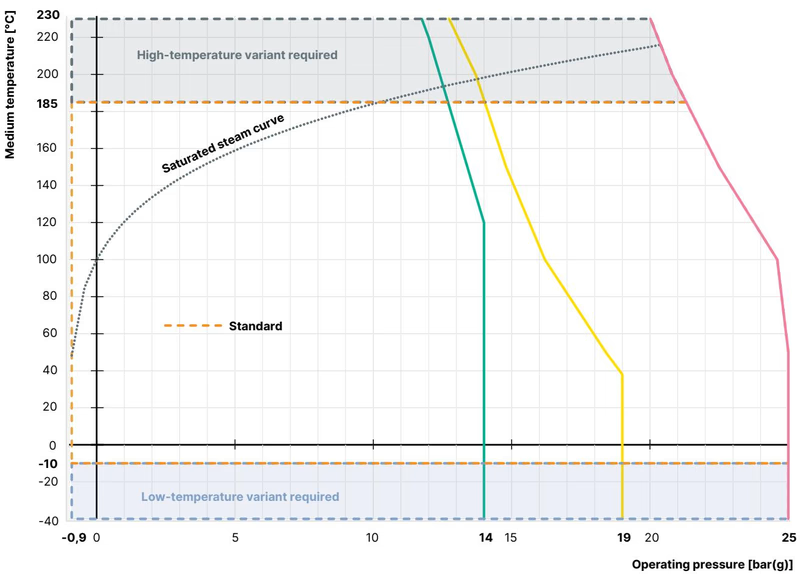
Derating the operating pressure as per DIN EN 12516-1/PN25
| Temperature [°C] | Pressure [bar] |
|---|---|
| -10...+50 | 25.0 |
| 100 | 24.5 |
| 150 | 22.4 |
| 200 | 20.3 |
| 230 | 19.0 |
WARNING
Danger from wear and tear on device If there is wear and tear, medium can leak out of the relief bore and people may be seriously injured. The relief bore must be regularly inspected for any medium leakages. If media are hazardous, safeguard the environment around the relief bore.
WARNING
Contaminated pilot air The control exhaust air of the device can be contaminated with lubricants and damage the health of people and the environment. Dissipate control exhaust air appropriately. Only use fresh air for generating compressed air for the device.
TIP
Installation Installation position is any, preferably with the actuator facing up. Note the flow direction and make sure that pipelines are in alignment. Remove any soiling from pipelines before installation.
Explore similar products in our catalog