PN25

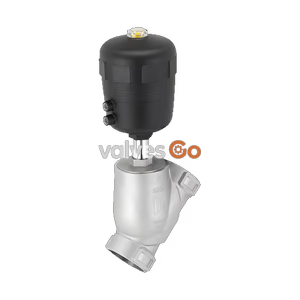
Burkert Type 2100 pneumatically operated 2/2-way angle seat valve (SKU 20084295) features a stainless steel body, PTFE seal, and handles pressures up to 25 bar.
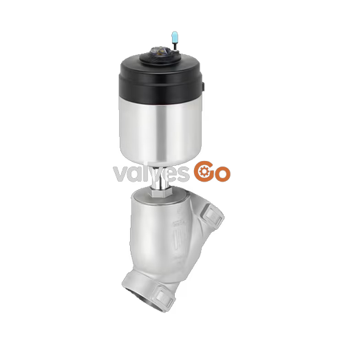
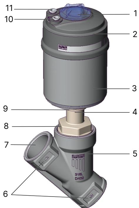
Burkert Type 2100 angle seat valve is optimised for decentralized process automation and fulfils strict criteria in process environments. The design allows integration of automation units in all expansion stages, from electrical/optical position feedback to pneumatic control and integrated fieldbus interfaces. The self-adjusting V-seal packing gland maintains tightness and extends service life. The integrated system of valve and automation unit features internal pilot air ducts, IP65/67 and NEMA Type 4X protection classes, and high chemical resistance.

| Property | Specification |
|---|---|
| Design | Angle seat valve |
| Nominal diameter | DN 10 to DN 80, NPS 3/8 to NPS 3 |
| Safety setting | Normally closed (control function A), normally open (control function B) |
| Flow direction | Flow to open (below seat), flow to close (above seat) |
| Operating pressure | 0 to 25 bar(g), vacuum variants to -0.9 bar(g) |
| Nominal pressure | PN 25 (DIN EN 1333), Class 150 (DIN EN 1759) |
| Medium temperature | -40 °C to +230 °C (SKU 20084295: -10 °C to 185 °C) |
| Ambient temperature | -10 °C to +100 °C |
| Viscosity | Max. 600 mm²/s |
| Control medium | Air, neutral gases |
WARNING
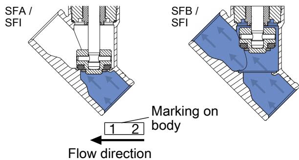
Risk of damage due to bursting pipes and bursting equipment when the flow is above the seat. In the case of liquid mediums, water hammer can occur causing pipes and the device to burst. Do not use valves with flow above the seat for liquid mediums.
Only use flow direction below the seat for liquid media, gases, and vapours. As the medium is present under the swivel plate, the operating pressure contributes to the opening of the valve.
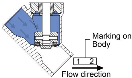
Only use flow direction above the seat for gases and vapours, and for valves with control function A (closed by spring force in rest position). As the medium is present above the swivel plate, the operating pressure contributes to the closing of the valve and supports the sealing of the valve seat.
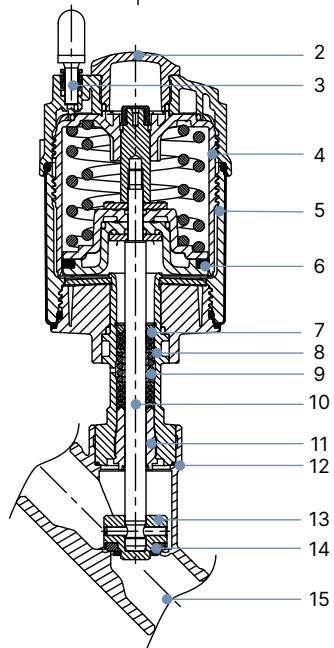
| Element | Material |
|---|---|
| Actuator cover | PPS |
| Actuator casing | Stainless steel 1.4561 (316Ti) |
| Piston seal | FKM |
| Spring | Stainless steel 1.4310 |
| Packing gland | PTFE V-Rings (filled), with spring compensation |
| Spindle | Stainless steel 1.4401 (316)/1.4404 (316L) |
| Spindle guide | PEEK |
| Swivel plate | Stainless steel 1.4401 (316)/1.4404 (316L) |
| Seat seal | PTFE, PEEK (Option) |
| Valve body | Stainless steel CF3M |
DANGER
Explosion Hazard due to Electrostatic Charge If the device has the code PX51, it is suitable for use as category 2 equipment in zones 1/21 and 2/22. Ensure the actuator and valve body are grounded. If using a plastic valve body, ground the actuator separately. Do not use magnetic coils in areas with strong charge-generating processes.
Explore similar products in our catalog