PN25

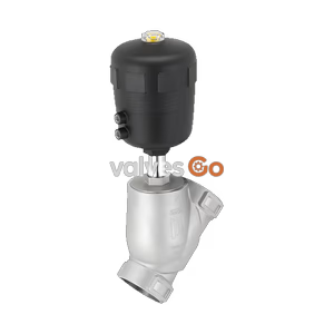
Burkert Type 2960 (Model 20088504) manually operated 2-way angle seat control valve. Features DN 50 clamp connection, stainless steel body, PTFE seal, and 0-25 bar pressure range.
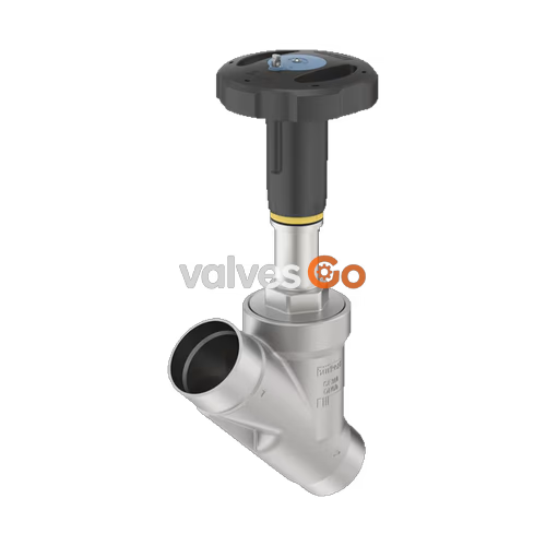
The Burkert 20088504 Type 2960 control valve consists of a manual actuator and an angle seat valve body made of high-quality stainless steel. A parabolic cone enables a flow capacity that is up to 35% higher compared to conventional control valves. The precise spindle guide enables control, even under demanding operating conditions. A soft PTFE seal guarantees reliable sealing. The actuator is made of high-quality plastic (PPS) and is suitable for use in demanding environments. It possesses a visual position indicator and is equipped with stroke limitation and locking. The packing gland uses tried-and-tested V-seals and possesses spring compensation, which means that it does not need to be pulled back manually.

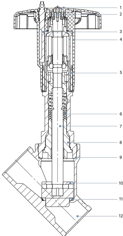
| No. | Element | Material |
|---|---|---|
| 1 | Cover | Polyamide (PA) |
| 2 | Screw | Stainless steel 1.4301 |
| 3 | Lock pin | Stainless steel 1.4305 |
| 4 | Handwheel | Polyphenylene sulfide (PPS) |
| 5 | Optical position indicator with scale | Polyamide (PA) |
| 6 | Packing gland | PTFE V-rings (filled), with spring compensation |
| 7 | Spindle | Stainless steel 1.4401 or 1.4404 |
| 8 | Spindle guide | Stainless steel 1.4404 (316L), PTFE filled |
| 9 | Body seal | Graphite |
| 10 | Control cone | 1.4571 (optionally hardened) |
| 11 | Seat seal | PTFE |
| 12 | Valve body | Stainless steel 316L/CF3M |
By manually overriding the handwheel, the force is transmitted via a spindle and the valve is opened or closed. Turning the handwheel anticlockwise opens the valve, turning it clockwise closes it. For the medium handwheel size (110 mm), the tightening torque must not exceed 15 Nm.
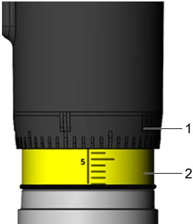
When turning the handwheel anticlockwise, the reproducible stroke scale becomes visible between the position indicator and the handwheel. The scale on the handwheel determines the rotation position of the handwheel (50 positions). The reproducible stroke scale shows, depending on the bottom edge of the handwheel, the relative position of the valve (valve opening) and acts as a fixation point for determining the rotation position.
Note on Stroke Scale
The visibility of the stroke scale is not directly correlated with the closed position of the valve. Depending on the valve design, the repeatable stroke scale may not be visible when the valve is open, or be visible when the valve is closed.
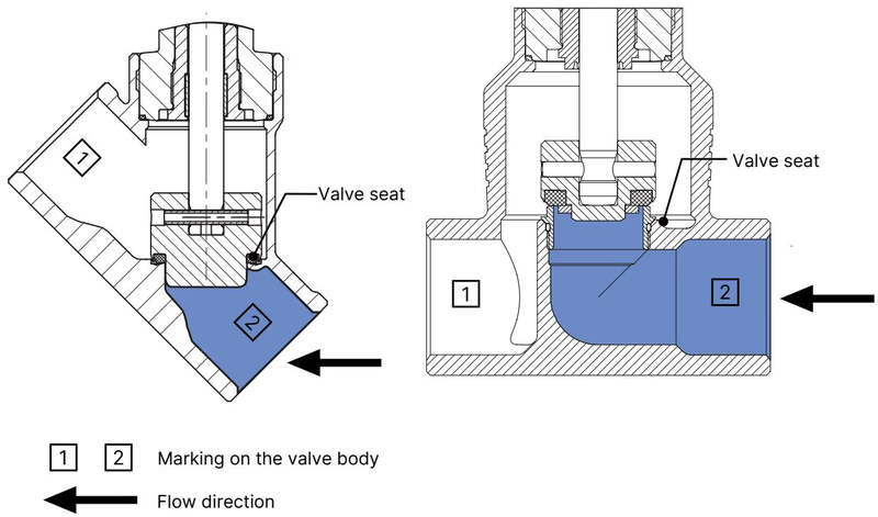
The valve seat is always closed against the medium flow. The flow direction should therefore be set such that the valve reaches the flow beneath the valve seat.
Risk of injury due to high pressure and escaping medium
Switch off the pressure before working on the device or system. Vent or drain the lines.
Risk of crushing by mechanically powered parts
Do not reach into the openings of the valve body.
When screwing the actuator into the valve body for a DN 50 valve, observe a tightening torque of 70 Nm (±3 Nm). Grease the external thread of the body connection with an approved lubricant (e.g., Klüberpaste UH1 96-402) before assembly.
Setting the minimum and maximum stroke limit is possible via an adjusting sleeve.
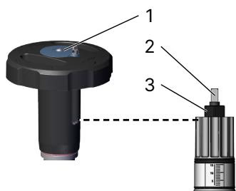
The handwheel can be locked to prevent unintentional or unauthorised operation. The medium handwheel size (110 mm) can be locked in 13 locking positions per revolution (every 27° corresponds to 0.13 mm of stroke).
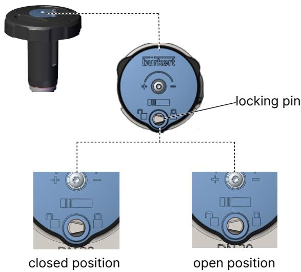
Push the locking pin down and rotate by 180°. The locking pin has a bore (Ø 3.8 mm) and can be secured against unauthorised use with a padlock.
When used in accordance with the operating instructions, the actuator of the manually operated valve is maintenance-free. Perform a visual inspection of the device once per year. If leaks occur, replace the respective wearing part. Muddy and abrasive media require correspondingly shorter inspection intervals.
Explore similar products in our catalog