


PN25

BURKERT 20111077 (Type 2961) is a manually operated 2-way globe control valve featuring DN 15 DIN EN 1092-1 PN 25 flanges, stainless steel 316L body, PEEK seat seal, equal percentage trim, and ATEX/IECEx certification.
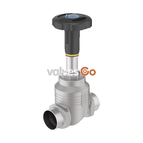
BURKERT 20111077 (Type 2961) is a manually operated 2-way globe control valve designed for demanding industrial flow control applications. The valve assembly pairs a manual rotary actuator with a stainless steel 316L/CF3M globe valve body equipped with DN 15 flanged connections according to DIN EN 1092-1 PN 25. Featuring a 15 mm replaceable seat orifice and an equal-percentage parabolic control cone, it achieves a nominal flow coefficient Kvs of 4.3 m³/h (Cv 5 gal/min) with a 50:1 theoretical rangeability. A soft PEEK seat seal ensures bubble-tight shut-off meeting DIN EN 60534-4 Leakage Class VI across operating pressures up to 25 bar(g) and media temperatures from -10 °C to +230 °C.
The manual actuator features a 45 mm polyphenylene sulphide (PPS) handwheel (Size S) and a spindle interface D10, incorporating a visual indicator system with a 50-division handwheel rotation dial and an exposed linear stroke scale for repeatable manual flow adjustments. The internal stem assembly is guided by a PTFE-filled stainless steel bush and sealed with a maintenance-free, spring-loaded PTFE V-ring gland packing. Certified under ATEX and IECEx for equipment category 2 (Zones 1/21 and 2/22), BURKERT 20111077 is rated for steam, water, neutral gases, oils, fuels, hydraulic fluids, alkalis, and organic solvents.
| Parameter | Specification |
|---|---|
| Valve Type | Manually operated 2-way globe control valve |
| Burkert Type / Article No. | Type 2961 / 20111077 |
| Nominal Diameter | DN 15 (1/2") |
| Port Connection | Flange according to DIN EN 1092-1 PN 25 (Face-to-face length FTF 1 per DIN EN 558-1) |
| Flow Direction | Flow to open (below seat) |
| Valve Body Material | Stainless steel 316L / CF3M |
| Seat Orifice Size | 15 mm (9/16") |
| Nominal Flow Coefficient | Kvs = 4.3 m³/h (Cv = 5 gal/min) |
| Flow Characteristic | Equal percentage, theoretical rangeability 50:1 |
| Operating Pressure Range | 0 bar(g) to 25 bar(g) |
| Nominal Pressure Class | PN 25 (DIN EN 1333), Class 150 (DIN EN 1759) |
| Seat Seal Material | PEEK (Polyetheretherketone) |
| Seat Leakage | Leakage Class VI according to DIN EN 60534-4:2006 |
| Medium Temperature Range | -10 °C to +230 °C |
| Ambient Temperature Range | -10 °C to +60 °C |
| Maximum Fluid Viscosity | 600 mm²/s |
| Gland Packing | Spring-compensated PTFE V-rings (filled) |
| Stem Diameter / Interface | Spindle D10 |
| Handwheel Size / Material | Size S (Ø 45 mm) / Polyphenylene sulphide (PPS) |
| Stroke Nominal Value | 19 mm (slope per revolution 1.25 mm) |
| Operating Media | Steam, water, neutral gases, alcohols, oils, fuels, hydraulic fluids, salt solutions, alkalis, organic solvents |
| Certification | ATEX / IECEx: II 2 G Ex h IIC T4...T2 Gb, II 2 D Ex h IIIC T135°C...T300°C Db |
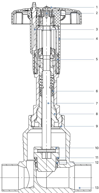
| Item | Component | Material |
|---|---|---|
| 1 | Cover | Polyamide (PA) |
| 2 | Screw | Stainless steel 1.4301 |
| 3 | Locking device | Stainless steel 1.4305 |
| 4 | Handwheel | Polyphenylene sulphide (PPS) |
| 5 | Visual position indicator with scale | Polyamide (PA) |
| 6 | Packing gland | PTFE V-rings (filled), with spring compensation |
| 7 | Stem | Stainless steel 1.4401 or 1.4404 |
| 8 | Spindle guide | Stainless steel 1.4404 (316L), PTFE filled |
| 9 | Housing seal | Graphite |
| 10 | Control cone | Stainless steel 1.4571 |
| 11 | Seat seal | PEEK |
| 12 | Valve seat with O-ring | Stainless steel 1.4571, EPDM |
| 13 | Valve body | Stainless steel 316L / CF3M |
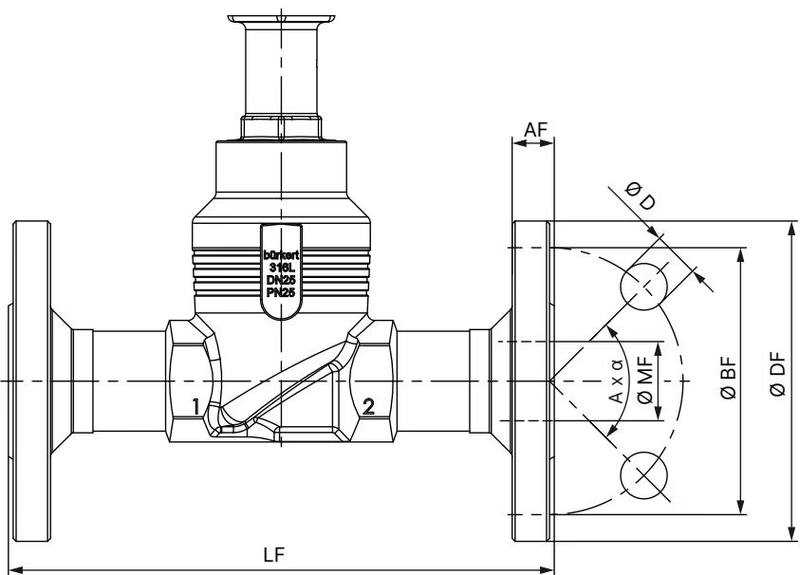
Dimensions are stated in mm in accordance with face-to-face series FTF 1 (DIN EN 558-1):
| DN | Outer Flange ∅ DF | Face-to-Face Length LF | Pitch Circle ∅ BF | Flange Thickness AF | Bolt Hole ∅ D | Bolt Pattern A x α | Neck Diameter ∅ MF |
|---|---|---|---|---|---|---|---|
| 15 | 95 mm | 130 mm | 65 mm | 16 mm | 14 mm | 4 × 90° | 18.1 mm |
For pipe size DN 15 (Handwheel Size S):
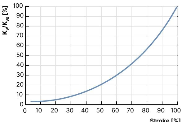
The Type 2961 valve follows an equal-percentage control characteristic conforming to DIN EN 60534-2-4. The theoretical rangeability (Kvs / Kv0) is 50:1. The smallest flow coefficient meeting the tilt tolerance ($K_{vR}$) is defined at 5% of stroke for orifices larger than 10 mm.
| Stroke (%) | Kv Value (m³/h) |
|---|---|
| 5% | 0.14 |
| 10% | 0.17 |
| 20% | 0.22 |
| 30% | 0.35 |
| 40% | 0.52 |
| 50% | 0.80 |
| 60% | 1.20 |
| 70% | 1.80 |
| 80% | 2.70 |
| 90% | 3.70 |
| 100% (Kvs) | 4.30 |
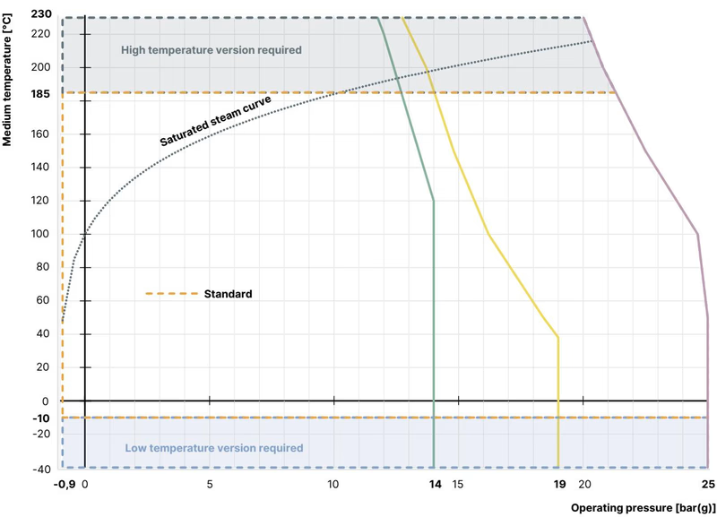
The permissible operating pressure is bounded by the valve body rating according to DIN EN 12516-1 (PN 25) across the medium temperature spectrum:
| Temperature (°C) | Maximum Permissible Operating Pressure (bar) |
|---|---|
| -10 °C to +50 °C | 25.0 bar |
| 100 °C | 24.5 bar |
| 150 °C | 22.4 bar |
| 200 °C | 20.3 bar |
| 230 °C | 19.0 bar |
Seat Sealing Performance
PEEK soft-sealing inserts yield DIN EN 60534-4 Leakage Class VI (bubble-tight closure), eliminating the necessity of an upstream isolation valve in standard service. PEEK is recommended for applications operating above +130 °C up to +230 °C.
Actuator Locking and Stroke Limitation
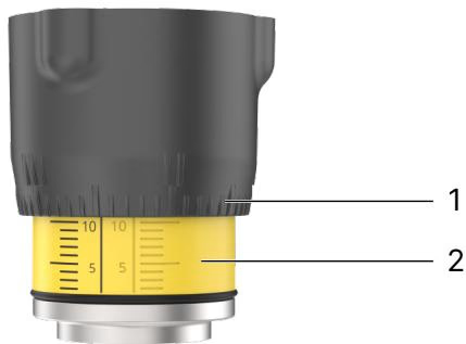
Optional configurations of the Type 2961 actuator allow stroke adjustment and position locking. Handwheel size S features 12 locking intervals per revolution (each 30° indexing equals 0.10 mm stroke travel), securable via a Ø 3.8 mm hole using an industrial padlock.
Safety Precaution
Depressurize and drain process lines completely before performing any disassembly or maintenance work on the valve assembly.
The manual actuator mechanism is maintenance-free under normal operating conditions. Inspect the valve externally and verify relief bore integrity once per year. Abrasive or contaminated media require shorter inspection intervals.
| Fault Symptom | Root Cause | Remedial Action |
|---|---|---|
| Valve does not seal tightly | Debris trapped between seal and seat | Clean seating surfaces; install an upstream strainer |
| Valve does not seal tightly | PEEK seat seal worn or damaged | Replace the plug/seal closure member |
| Valve does not seal tightly | Flow direction reversed | Reinstall valve adhering to body flow arrow |
| Valve does not seal tightly | Operating pressure exceeds limits | Verify process pressure against rating curve |
| Leakage at relief bore | Spindle gland packing worn | Replace gland packing assembly |
BURKERT 20111077 complies with mechanical explosion protection code PX51 (EPS 18 ATEX 2 008 X / IECEx EPS 18.0007 X) as Category 2 mechanical equipment suitable for Zone 1/21 and Zone 2/22:
| Temperature Class | Maximum Permissible Surface Temperature | Ambient Temperature Range | Maximum Medium Temperature |
|---|---|---|---|
| T4 | +135 °C | -40 °C to +100 °C | +125 °C |
| T3 | +200 °C | -40 °C to +130 °C | +185 °C |
| T2 | +300 °C | -40 °C to +130 °C | +285 °C |
Potential Electrostatic Charging Hazard
Clean the device only with a damp or anti-static cloth to avoid electrostatic sparking. The metallic valve body must be grounded to the pipeline system to ensure continuous equipotential bonding.
Explore similar products in our catalog



