
PN25

BURKERT 20122955 Type 2961 is a manually operated DN 40 globe control valve with ASME BPE clamp connections, PPS handwheel, PTFE seat seal, Kv 17.8 m³/h, and PN 25 rating for steam, liquids, and gases.
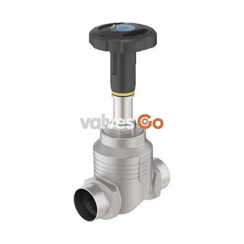
BURKERT 20122955 Type 2961 is a manually operated 2-way globe control valve engineered for the continuous throttling and isolation of neutral gases, steam, water, alcohols, fuels, and chemical process fluids. Fabricated with a cast 316L stainless steel body and ASME BPE clamp connections (DN 40 / NPS 1 1/2, pipe 38.1 x 1.65 mm, clamp collar 50.5 mm), the valve features an exchangeable 32 mm stainless steel seat paired with a parabolic control cone. Operating under flow-below-seat orientation (flow to open), the assembly achieves a water flow factor Kv of 17.8 m³/h (Cv 20.7 gpm) with an equal percentage flow profile and a 50:1 theoretical rangeability.
Process pressure capability extends from 0 to 25 bar(g) (PN 25 / Class 150 rating), governed by temperature derating standards. A soft PTFE seat seal provides bubble-tight shut-off meeting DIN EN 60534-4 Leakage Class VI across fluid temperatures from -10 °C to +130 °C. Manual actuation is delivered through an engineering plastic PPS handwheel (size M, 110 mm outer diameter, 1.75 mm stroke advance per revolution) featuring an integrated optical position indicator and an external reproducible stroke scale subdivided into 50 rotation increments. The stem seal assembly incorporates spring-compensated PTFE V-rings that automatically maintain live-loaded packing compression without manual repacking.

| Specification Parameter | Value / Range |
|---|---|
| Product Identity | Manually operated 2-way globe control valve |
| Valve Type / Article Number | Type 2961 / 20122955 |
| Nominal Port Diameter | DN 40 (NPS 1 1/2) |
| Pipe Connection Geometry | ASME BPE / BS4825-3 (Tube 38.1 x 1.65 mm, Clamp Flange ∅ 50.5 mm) |
| Valve Body Material | Stainless steel 316L / CF3M |
| Seat Orifice Diameter | 32 mm (1 1/4") |
| Rated Flow Coefficient (Kv) | 17.8 m³/h (DIN EN 60534-2-4 test standard with water) |
| Rated Flow Coefficient (Cv) | 20.7 gpm |
| Flow Characteristic / Rangeability | Equal percentage / 50:1 theoretical |
| Seat Leakage Class | DIN EN 60534-4 Class VI (soft seal) |
| Nominal Operating Pressure | PN 25 (DIN EN 1333) / Class 150 (DIN EN 1759), max. 25 bar(g) |
| Fluid Temperature Range | -10 °C to +130 °C (PTFE seat seal limit) |
| Ambient Operating Temperature | -10 °C to +60 °C |
| Permissible Fluid Viscosity | Max. 600 mm²/s |
| Permissible Process Media | Steam, water, neutral gases, alcohols, oils, fuels, hydraulic fluids, salt solutions, alkalis, organic solvents |
| Flow Direction | Flow to open (under seat) |
| Handwheel Size / Diameter | Size M / ∅ 110 mm (slope 1.75 mm per revolution) |
| Actuator Interface | Spindle D14 |
| Optical Indication | External reproducible stroke scale + 50-increment handwheel rotation scale |
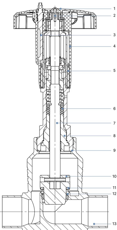
| Item No. | Component Part | Material Specification |
|---|---|---|
| 1 | Cover | Polyamide (PA) |
| 2 | Fastening Screw | Stainless steel 1.4301 |
| 3 | Locking Device (optional) | Stainless steel 1.4305 |
| 4 | Manual Handwheel | Polyphenylene sulphide (PPS) |
| 5 | Visual Position Indicator with Scale | Polyamide (PA) |
| 6 | Packing Gland | Filled PTFE V-rings with spring compensation |
| 7 | Stem (Spindle) | Stainless steel 1.4401 or 1.4404 |
| 8 | Spindle Guide | Stainless steel 1.4404 (316L), PTFE filled |
| 9 | Housing Bonnet Seal | Graphite |
| 10 | Control Cone | Stainless steel 1.4571 (optionally hardened) |
| 11 | Seat Seal | PTFE (soft seal, -10 °C to +130 °C) |
| 12 | Valve Seat with O-Ring | Stainless steel 1.4571, EPDM |
| 13 | Valve Body | Cast stainless steel 316L / CF3M |
| Nominal Connection Size DN | Nominal Size NPS | Handwheel Diameter ∅ [mm] | Height H1 [mm] | Height H2 with Locking [mm] |
|---|---|---|---|---|
| 15 | 1/2 | 45 (Size S) | 217 | 224 |
| 20 | 3/4 | 45 (Size S) | 224 | 230 |
| 25 | 1 | 45 (Size S) | 228 | 234 |
| 32 | 1 1/4 | 110 (Size M) | 296 | 303 |
| 40 | 1 1/2 | 110 (Size M) | 301 | 307 |
| 50 | 2 | 110 (Size M) | 307 | 313 |
| 65 | 2 1/2 | 160 (Size L) | 361 | 368 |
| 80 | 3 | 160 (Size L) | 369 | 375 |
| 100 | 4 | 160 (Size L) | 379 | 385 |
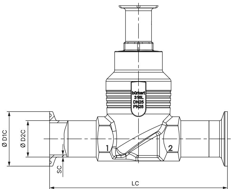
| Connection NPS | Port Size DN | Face-to-Face LC [mm] | Pipe Outer ∅ D2 C [mm] | Flange Outer ∅ D1 C [mm] | Wall Thickness SC [mm] |
|---|---|---|---|---|---|
| 1/2 | 15 | 122 | 12.7 | 25.0 | 1.65 |
| 3/4 | 20 | 126 | 19.05 | 25.0 | 1.65 |
| 1 | 25 | 126 | 25.4 | 50.5 | 1.65 |
| 1 1/2 | 40 | 172 | 38.1 | 50.5 | 1.65 |
| 2 | 50 | 182 | 50.8 | 64.0 | 1.65 |
| 2 1/2 | 65 | 231 | 63.5 | 77.5 | 1.65 |
| 3 | 80 | 265 | 76.2 | 91.0 | 1.65 |
| 4 | 100 | 315 | 101.6 | 119.0 | 2.11 |
| Nominal Body Size DN | Tightening Torque [Nm] | Permissible Tolerance [Nm] |
|---|---|---|
| 10 / 15 | 45 | ±3 |
| 20 | 50 | ±3 |
| 25 | 60 | ±3 |
| 32 | 65 | ±3 |
| 40 | 65 | ±3 |
| 50 | 70 | ±3 |
| 65 | 100 | ±3 |
| 80 | 120 | ±5 |
| 100 | 150 | ±5 |
Flow control conforms to DIN EN 60534-2-4 standards. The flow must enter below the valve seat (flow to open), which prevents fluid hammer during manual closing. For valve seat sizes above 10 mm, the minimum controllable flow value KvR is established at 5% of total valve travel.
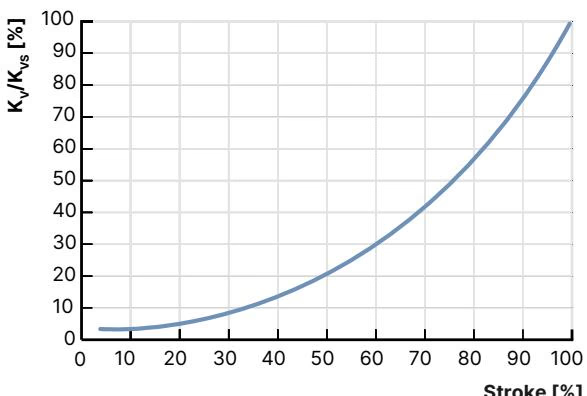
| Pipe DN | Pipe NPS | Seat Size [mm] | Handwheel Size | Max Pressure [bar(g)] | Rangeability | 5% | 10% | 20% | 30% | 40% | 50% | 60% | 70% | 80% | 90% | 100% (Kvs) |
|---|---|---|---|---|---|---|---|---|---|---|---|---|---|---|---|---|
| 40 | 1 1/2 | 25 | 110 (M) | 25 (VI) | 50:1 | 0.40 | 0.50 | 0.75 | 1.1 | 1.7 | 2.6 | 3.8 | 5.6 | 8.0 | 10.7 | 13.6 m³/h |
| 40 | 1 1/2 | 32 | 110 (M) | 25 (VI) | 50:1 | 0.48 | 0.60 | 0.85 | 1.3 | 2.1 | 3.2 | 4.6 | 6.9 | 11.0 | 15.0 | 20.0 m³/h |
| 40 | 1 1/2 | 40 | 110 (M) | 25 (VI) | 50:1 | 0.60 | 0.70 | 1.1 | 1.7 | 2.7 | 4.0 | 6.0 | 9.2 | 13.8 | 18.2 | 23.8 m³/h |
Nominal Flow Factor Note
The standard full-stroke Kvs value of the DN 40 / 32 mm seat trim reaches 20.0 m³/h under open pipeline conditions; product configuration 20122955 is factory calibrated to a certified water flow rating of 17.8 m³/h (20.7 gpm) at 1 bar differential pressure.
Process line pressure limits decrease at elevated temperatures in accordance with DIN EN 12516-1 and ASME B16.34 standards.
| Temperature [°C] | DIN EN 12516-1 / PN 25 Max Pressure [bar] | ASME B16.34 Cl. 150 Max Pressure [bar] |
|---|---|---|
| -10 to +38 | 25.0 | 19.0 |
| +50 | 25.0 | 18.4 |
| +100 | 24.5 | 16.2 |
| +130 (PTFE Max) | 23.2 | 15.4 |
| +150 | 22.4 | 14.8 |
| +200 | 20.3 | 13.7 |
| +230 | 19.0 | 12.7 |
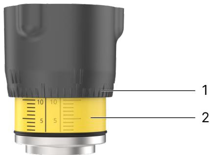
Turning the handwheel counterclockwise lifts the stem and exposes the reproducible stroke scale between the actuator mounting gland and the bottom edge of the handwheel. The circumference of the handwheel features an integrated 50-division dial, allowing precise, reproducible throttling setpoints in combination with the vertical stroke scale.
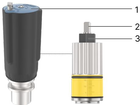
Minimum and maximum mechanical stroke limits can be set by adjusting the internal sleeve:
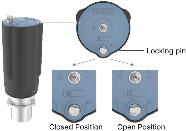
Size M handwheels support 13 distinct locking detents per 360° rotation (every 27° of handwheel rotation corresponds to 0.13 mm of linear stroke). The locking pin incorporates a 3.8 mm cross-bore designed to receive a safety lockout padlock.
Lockout Sealing Caution
Pressing and rotating the locking pin 180° secures the mechanical position against unauthorized manipulation. Locking the handwheel in the closed position does not guarantee DIN EN 60534-4 Leakage Class VI isolation under all thermal transient conditions.
Pressure Hazard
Prior to servicing, depressurize the piping system completely, drain all process media, and vent fluid lines. Flush thoroughly if toxic, caustic, or aggressive chemicals were handled.
| Fault Condition | Root Cause | Corrective Action |
|---|---|---|
| Valve does not seal tightly across the seat | Particulate contamination between seat ring and PTFE plug | Disassemble and install an upstream strainer / dirt trap |
| Valve seat seal worn or deformed | Replace the control cone and seal assembly | |
| Pipeline flow direction inverted | Reverse valve installation to align flow with body arrow | |
| Line pressure exceeds maximum specification | Reduce operating pressure to conform with type label rating | |
| Medium escapes through actuator relief bore | Stem packing gland worn or degraded | Replace packing gland seal set (PTFE V-rings) |
When ordered with variable code PX51, Type 2961 is certified as non-electrical mechanical equipment for Zone 1/21 and Zone 2/22 (II 2G Ex h IIC T4...T2 Gb / II 2D Ex h IIIC T135 °C...T300 °C Db under EPS 18 ATEX 2 008 X and IECEx EPS 18.0007X).
| Temperature Class | Maximum Permissible Surface Temperature | Ambient Temperature Range | Maximum Permissible Medium Temperature |
|---|---|---|---|
| T2 | +300 °C | -40 °C to +130 °C | +285 °C |
| T3 | +200 °C | -40 °C to +130 °C | +185 °C |
| T4 | +135 °C | -40 °C to +100 °C | +125 °C |
Electrostatic Charge Hazard in Hazardous Areas
Conductive piping sections and metallic components must be bonded to earth ground via grounding straps or terminal lugs. Clean external plastic surfaces exclusively with a damp cloth to prevent electrostatic discharge.
Explore similar products in our catalog