


PN25

Burkert 20126691 Type 2100 is a pneumatically operated 2/2-way angle seat valve with DN 50 ASME BPE clamp ends, normally closed CFA flow-above-seat operation, PPS actuator, and PTFE seat.
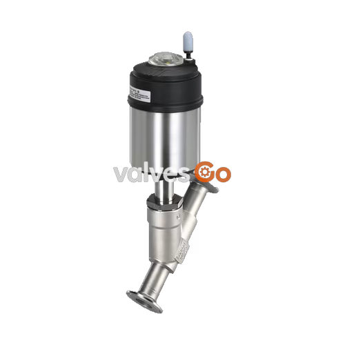
Burkert 20126691 Type 2100 is a pneumatically operated 2/2-way angle seat shut-off valve designed for decentralized process automation in hygienic, steam, and gas applications. Configured under control function A, the valve is normally closed by spring force in the rest position and utilizes a flow-above-seat arrangement where medium pressure assists the spring in maintaining tight closure across the valve seat. Port connections are standard 2 inch (DN 50) ASME BPE sanitary clamp ends with a 64.0 mm flange diameter and an overall face-to-face laying length of 230 mm.
Constructed with an investment cast CF3M stainless steel body, an integrated stainless steel 1.4561 (316Ti) actuator casing with a polyphenylene sulphide (PPS) cover, and pure PTFE seat sealing, Burkert 20126691 delivers a water flow coefficient Kv of 49 m³/h. The valve handles medium operating pressures from 0 to 12 bar(g) and fluid temperatures from -10 °C to +185 °C. Wetted parts are compliant with Regulation (EC) 1935/2004 and FDA requirements according to the manufacturer declaration, and the assembly is certified for Clean-in-Place (CIP) and Steam-in-Place (SIP) thermal regimes.

| Parameter | Specification Details |
|---|---|
| Article Number | 20126691 |
| Valve Type | 2100 ELEMENT |
| Construction | 2/2-way angle seat valve complete |
| Control Function | Control function A (normally closed by internal spring force) |
| Flow Direction | Flow above seat (flow-to-close) |
| Nominal Diameter | DN 50 (seat diameter 50 mm, body nominal size 50 mm, 2 inch) |
| Flow Coefficient Kv (Water, +20 °C) | 49 m³/h |
| Operating Pressure Range | 0.00 bar(g) to 12.00 bar(g) |
| Nominal Pressure Class | PN 25 (DIN EN 1333), Class 150 (DIN EN 1759) |
| Minimum Pilot Pressure | 2.7 bar(g) (dependent on line pressure, see diagram) |
| Maximum Pilot Pressure | 7.0 bar(g) (rating up to 10 bar(g) for actuator 70 mm) |
| Pilot Fluid Connection | Push-in connector for external Ø 6 mm or 1/4 inch tubing |
| Actuator Size | 70 mm (M) |
| Medium Temperature Range | -10 °C to +185 °C |
| Ambient Temperature Range | -10 °C to +60 °C (push-in pneumatic connector limit) |
| Seat Leakage Class | Rate A according to DIN EN 12266-1 (test medium air) |
| Protection Class | IP65 / IP67, NEMA Type 4X |
| Food Contact Compliance | EC Regulation 1935/2004, FDA compliant wetted materials |
| Cleaning Capabilities | CIP capable, SIP capable |
Burkert Type 2100 uses high-alloy stainless steel and polymer sealing systems to resist chemical exposure and ensure zero external leakage through its self-adjusting packing gland.
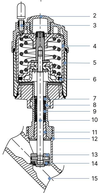
| Item | Component | Material |
|---|---|---|
| 1 | Ground terminal | Stainless steel 1.4301 / 1.4305 (ATEX variants) |
| 2 | Optical position indicator | Polysulfone (PSU) |
| 3 | Pilot air ports | Polypropylene (PP) push-in connector (G 1/8 stainless steel optional) |
| 4 | Actuator cover | Polyphenylene sulphide (PPS) |
| 5 | Actuator casing | Stainless steel 1.4561 (316Ti) |
| 6 | Piston seal | Fluoroelastomer (FKM) |
| 7 | Spring assembly | Stainless steel 1.4310 |
| 8 | Guide pipe | Stainless steel 1.4401 (316) / 1.4404 (316L) |
| 9 | Packing gland | Filled PTFE V-rings with spring compensation |
| 10 | Valve spindle | Stainless steel 1.4401 (316) / 1.4404 (316L) |
| 11 | Spindle guide | Polyether ether ketone (PEEK) |
| 12 | Body seal | Graphite (PTFE optional) |
| 13 | Swivel plate | Stainless steel 1.4401 (316) / 1.4404 (316L) |
| 14 | Seat seal | Pure Polytetrafluoroethylene (PTFE) |
| 15 | Valve body | Stainless steel CF3M (cast 316L equivalent) |
Lubricant Compliance
Lubricants utilized in the valve packing gland and pneumatic actuator assembly are certified and classified according to NSF H1 for incidental food contact.
Burkert 20126691 features integrated ASME BPE sanitary clamp ferrules welded directly to the investment cast valve body.
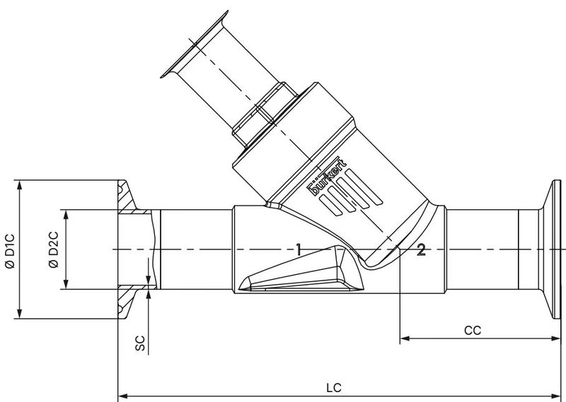
| Dimension Parameter | Symbol | Value (mm) | Value (inch) |
|---|---|---|---|
| Nominal Port Diameter | DN / NPS | DN 50 | 2" |
| Overall Face-to-Face Length | LC | 230 mm | 9.06" |
| Body Port Center to Face | CC | 77.5 mm | 3.05" |
| Clamp Flange Outer Diameter | Ø D1 C | 64.0 mm | 2.52" |
| Pipe Outer Diameter | Ø D2 C | 50.8 mm | 2.00" |
| Pipe Wall Thickness | SC | 1.65 mm | 0.065" |
| Port Inner Diameter | ID | 47.5 mm | 1.87" |
| Actuator Outer Diameter | Ø A | 91 mm | 3.58" |
| Actuator Height from Centerline | B | 223 mm | 8.78" |
| Total Valve Height | H | 219 mm | 8.62" |
| Clearance to Actuator Center | K/M | 196 mm | 7.72" |
| Height with Type 8690 / 8697 Control Unit | B/H | 274 mm | 10.79" |
| Height with Type 8691 / 8695 Control Head | B/H | 297 mm | 11.69" |
Burkert 20126691 utilizes a flow-above-the-seat configuration (flow-to-close). Because medium line pressure acts directly against the upper side of the swivel plate, process pressure actively contributes to valve closing and reinforces the tight sealing of the PTFE seat.
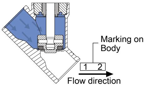
Flow Direction Medium Restriction
Risk of injury due to bursting pipes and equipment damage when media flow enters above the seat. In liquid service, closing against flowing liquid induces severe water hammer capable of rupturing pipelines and valve housings. Valves configured with flow above the seat must only be installed in steam and gaseous media systems.
To actuate the valve open, pilot air pressure must overcome both the mechanical spring force and the opposing line pressure acting downward on the swivel plate. For actuator size 70 mm (M) on DN 50 valves, the maximum permissible medium pressure is 12 bar(g).
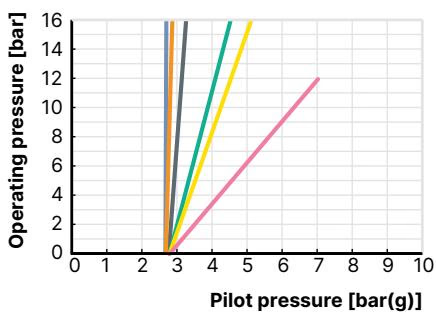
| Operating Line Pressure [bar(g)] | Minimum Pilot Pressure Required [bar(g)] |
|---|---|
| 0 bar | 2.7 bar |
| 4 bar | 3.8 bar |
| 8 bar | 5.2 bar |
| 12 bar | 6.8 bar |
Pressure retention capabilities are constrained by medium temperature according to ASME B16.34 Class 150 and DIN EN 12516-1 PN 25 ratings.
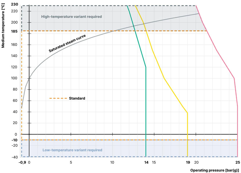
| Process Medium Temperature | Maximum Allowable Working Pressure (ASME B16.34 Cl. 150) | Maximum Allowable Working Pressure (DIN EN 12516-1 PN 25) |
|---|---|---|
| -29 °C to +38 °C | 19.0 bar(g) | 25.0 bar(g) |
| +50 °C | 18.4 bar(g) | 25.0 bar(g) |
| +100 °C | 16.2 bar(g) | 24.5 bar(g) |
| +150 °C | 14.8 bar(g) | 22.4 bar(g) |
| +185 °C | 13.9 bar(g) | 20.9 bar(g) |
| +200 °C | 13.7 bar(g) | 20.3 bar(g) |
Ambient Temperature Boundary
Because article 20126691 includes polypropylene push-in pneumatic connections, maximum ambient temperature is capped at +60 °C. The maximum continuous process fluid temperature rating is +185 °C.
Prior to mounting in piping, clean all lines of particulate matter. The valve may be mounted in any orientation, preferably with the actuator oriented vertically upward.
When servicing internal packings or replacing seating components, the actuator must be separated from the body connection:
Pneumatic ports 1 and 2 can be adjusted 360° to accommodate pipe runs. Pressurize pilot air port 1 to 5 bar to retract the swivel plate, place an open-end wrench on the body connection hex to hold it stationary, and rotate the drive connection hexagon in the approved clockwise tightening direction to the desired angle.
Routine inspection requires monitoring three primary locations:
| Fault Condition | Probable Cause | Corrective Action |
|---|---|---|
| Actuator fails to open | Pilot air pressure below 2.7 bar threshold | Increase pilot air supply pressure within 2.7 to 7.0 bar |
| Actuator fails to open | Process medium pressure exceeds 12 bar limit | Regulate line pressure within specified operating range |
| Actuator fails to open | Pilot air connected to exhaust port 2 | Connect pilot air supply tubing to pilot air port 1 |
| Valve seat fails to seal | Medium trapped debris across seat face | Flush line or remove actuator to clean seating surface |
| Valve seat fails to seal | Worn or scored PTFE seat disc | Install a replacement swivel plate assembly |
| Leakage at relief bore | Damaged spindle packing V-rings | Replace packing gland cartridge using 19 mm socket tool 683221 |
Explore similar products in our catalog



