PN25

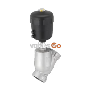
Burkert 20135094 (Type 2101) 2/2-way pneumatic globe valve. Features stainless steel actuator, weld end connection, PEEK seal, and CFA normally closed function. Handles up to 14 bar and 185°C.
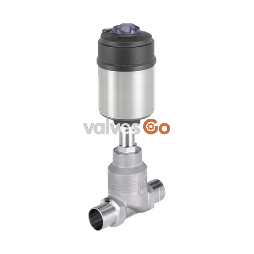
Burkert 20135094 (Type 2101) is a pneumatically operated 2/2-way globe valve specially optimised for decentralised process automation. It meets all practical requirements even under difficult operating conditions. Its unique design allows easy integration of automation units in all expansion stages. Maximum service life and tightness are achieved by the proven self-adjusting v-seal packing gland. The highly integrated system of valve and automation unit is characterised by its compact and smooth design, integrated pilot air ducts, protection classes IP65/67, NEMA Type 4X, and high resistance to chemicals.
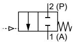
Control function A (CF A) Pneumatically operated 2/2-way on/off valve. Flow direction below seat. Normally closed by spring force.
WARNING
Risk of damage due to bursting pipes and bursting equipment when the flow is above the seat. In the case of liquid mediums, water hammer can occur causing pipes and the device to burst. Do not use valves with flow above the seat for liquid mediums.
Stainless steel for higher drive forces
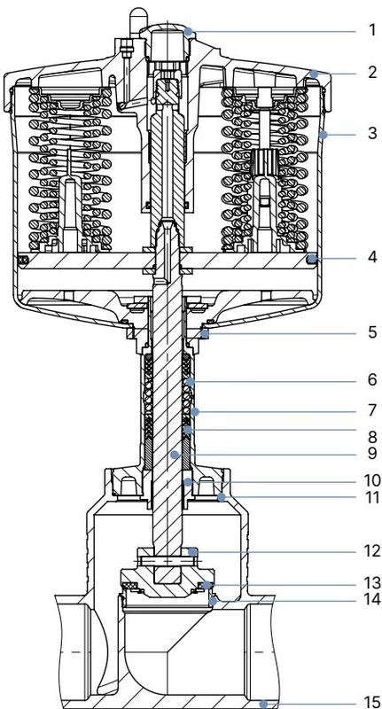
| No. | Element | Material |
|---|---|---|
| 1 | Transparent cover | Ultrason S |
| 2 | Drive cover | Stainless steel 1.4308 |
| 3 | Liner | Stainless steel 1.4404 |
| 4 | Piston seal | FKM |
| 5 | Nut | Stainless steel 1.4301 |
| 6 | Spring | Stainless steel 1.4310 |
| 7 | Tube | Stainless steel CF3M |
| 8 | Packing gland | PTFE V-rings (filled), with spring compensation |
| 9 | Stem | Stainless steel 1.4021 |
| 10 | Stem guide | Stainless steel 1.4404 (316L) / PTFE filled |
| 11 | Housing seal | Graphite or PTFE |
| 12 | Swing disc | Stainless steel 1.4401 (316)/ 1.4404 (316L) |
| 13 | Seat seal | PTFE or PEEK (option) |
| 14 | Valve seat with O-ring | Stainless steel 1.4571, EPDM |
| 15 | Valve body | Stainless steel 316L/CF3M |
Actuator
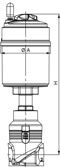
Body with welded connection
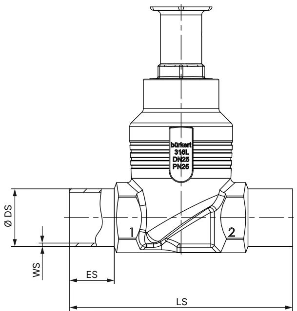
| Nominal diameter (port connection) DN | ES ∅ DS | LS WS | DIN EN ISO 1127 / ISO 4200 / DIN 11866 series B ∅ DS | WS |
|---|---|---|---|---|
| 100 | 26 | 260 | 114.3 | 2.6 |
(Note: Table shows specific dimensions for DN100 / 114.3mm ISO 4200 weld end)
Fluidic data for flow below seat

DANGER
Risk of injury from high pressure in the system or device. Before working on the system or device, switch off the pressure and ventilate or empty the lines.
WARNING
Valve leak if there is too little minimum pilot pressure or high operating pressure! Minimum pilot pressure that is too low, or failing to meet the permitted operating pressure, can cause a leak in the valve seat. Adhere to minimum pilot pressure and do not exceed the operating pressure.
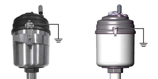
Special conditions in potentially explosive areas (ATEX):
Explore similar products in our catalog