


PN25

BURKERT 20135264 Type 2961 is a manually operated 2-way globe control valve with DN25 SMS 3008 welded ends, stainless steel body, PTFE seat seal, Kv 2.8 m3/h, and PN25 pressure rating.
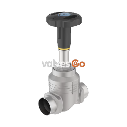
BURKERT 20135264 (Type 2961) is a manually operated 2-way globe control valve designed for accurate continuous flow adjustment of liquids, steam, and gases. Built with a cast stainless steel 316L/CF3M globe valve body and welded pipe ends according to SMS 3008 (DN 25, 25.0 x 1.2 mm), the valve pairs with an ergonomic plastic manual actuator made from polyphenylene sulphide (PPS). The valve incorporates a 10 mm (3/8") replaceable seat orifice and an equal percentage parabolic control plug, delivering a rated flow coefficient Kv of 2.8 m³/h (Cv 3.2 gpm) with a 50:1 theoretical control rangeability.

Equipped with a soft PTFE seat seal, BURKERT 20135264 achieves bubble-tight shut-off meeting Leakage Class VI in accordance with DIN EN 60534-4. The valve stem assembly relies on a self-adjusting PTFE V-ring packing gland with integrated spring compensation, preventing external leakage without necessitating manual packing adjustments during routine operation. Medium-contacting materials comply with FDA regulations and Regulation (EC) 1935/2004, making this configuration suitable for sanitary processing, pure steam, hot water, and aggressive media across operating pressures up to 25 bar(g).
BURKERT 20135264 controls media flow through manual rotation of the PPS handwheel. Rotary movement transfers through a stainless steel spindle (spindle diameter D10) to reposition the parabolic plug relative to the replaceable orifice seat. Flow direction is strictly directed below the seat (flow-to-open), ensuring positive shut-off against media pressure and minimizing pressure-induced vibration.
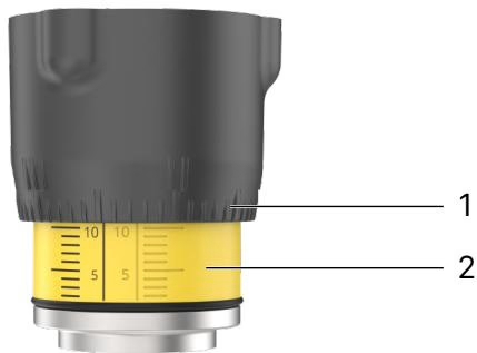
Position Indicator Reading
The outer rim of the handwheel provides 50 division steps per revolution. Turning the handwheel counter-clockwise exposes the reproducible stroke scale between the bonnet attachment and the handwheel. This dual-scale combination allows operators to record and repeat exact throttling points.
| Parameter | Technical Value |
|---|---|
| Article Number | 20135264 |
| Type Family | 2961 |
| Valve Configuration | 2/2-way globe control valve |
| Nominal Port Diameter | DN 25 (NPS 1) |
| Pipe Connection Standard | Welded to SMS 3008 (Tube 25.0 x 1.2 mm) |
| Pressure Rating | PN 25 (DIN EN 1333) / Class 150 (DIN EN 1759) |
| Operating Pressure Range | 0 bar(g) to 25 bar(g) |
| Nominal Seat Diameter | 10 mm (3/8") |
| Water Flow Coefficient Kv | 2.8 m³/h |
| Flow Coefficient Cv | 3.2 gpm |
| Seat Leakage Rate | Class VI (DIN EN 60534-4) |
| Flow Characteristic | Equal percentage (theoretical rangeability 50:1) |
| Flow Direction | Below seat (flow-to-open) |
| Medium Temperature Range | -10 °C to +130 °C (PTFE seat limit) |
| Ambient Temperature Range | -10 °C to +60 °C |
| Maximum Medium Viscosity | Up to 600 mm²/s |
| Permissible Fluid Media | Steam, water, neutral gases, alcohols, oils, fuels, salt solutions, alkalis, organic solvents |
| Food & Hygienic Compliance | FDA (Code of Federal Regulations), Regulation (EC) 1935/2004 |
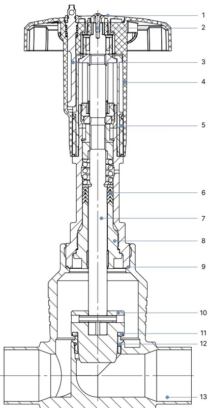
| Item | Component | Material Specification |
|---|---|---|
| 1 | Actuator Cover | Polyamide (PA) |
| 2 | Fastening Screw | Stainless steel 1.4301 |
| 3 | Locking Mechanism (optional) | Stainless steel 1.4305 |
| 4 | Handwheel | Polyphenylene sulphide (PPS) |
| 5 | Position Indicator with Scale | Polyamide (PA) |
| 6 | Packing Gland | Filled PTFE V-rings with spring compensation |
| 7 | Stem (Spindle) | Stainless steel 1.4401 or 1.4404 |
| 8 | Spindle Guide Bushing | Stainless steel 1.4404 (316L), PTFE-filled |
| 9 | Body Seal | Graphite |
| 10 | Control Cone (Plug) | Stainless steel 1.4571 |
| 11 | Seat Seal | PTFE (soft seal, Article 20135264) |
| 12 | Valve Seat Orifice with O-ring | Stainless steel 1.4571 with EPDM O-ring |
| 13 | Valve Body | Cast stainless steel 316L / CF3M |
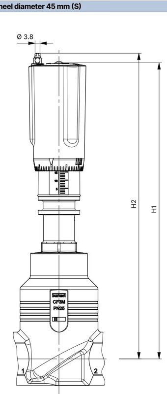
BURKERT 20135264 utilizes manual actuator size S with a 45 mm handwheel diameter. For nominal pipe size DN 25, the vertical envelope dimensions are detailed below:
| Pipe Connection Size | Handwheel Size | Handwheel Diameter ∅ | Height H1 (Standard) | Height H2 (with Locking) |
|---|---|---|---|---|
| DN 15 (NPS 1/2) | S | 45 mm | 217 mm | 224 mm |
| DN 20 (NPS 3/4) | S | 45 mm | 224 mm | 230 mm |
| DN 25 (NPS 1) | S | 45 mm | 228 mm | 234 mm |
| DN 32 (NPS 1 1/4) | M | 110 mm | 296 mm | 303 mm |
| DN 40 (NPS 1 1/2) | M | 110 mm | 301 mm | 307 mm |
| DN 50 (NPS 2) | M | 110 mm | 307 mm | 313 mm |
| DN 65 (NPS 2 1/2) | L | 160 mm | 361 mm | 368 mm |
| DN 80 (NPS 3) | L | 160 mm | 369 mm | 375 mm |
| DN 100 (NPS 4) | L | 160 mm | 379 mm | 385 mm |
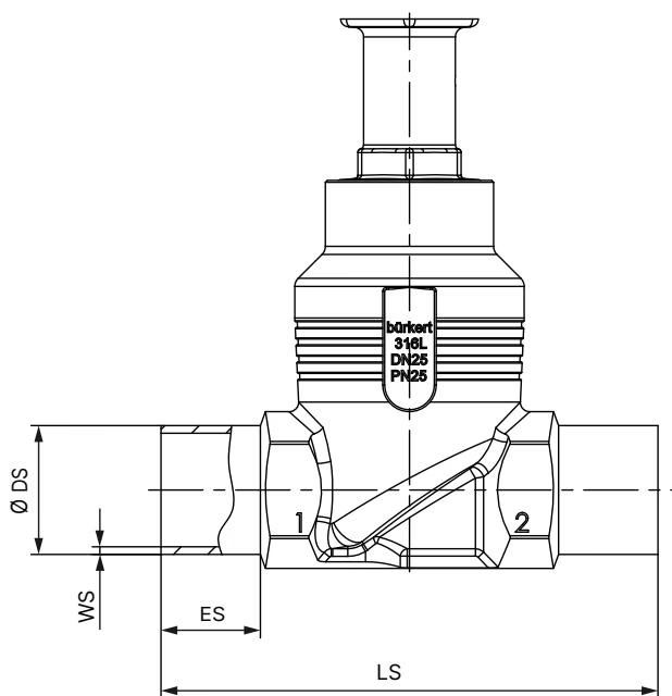
BURKERT 20135264 features welded tube dimensions of 25.0 x 1.2 mm according to SMS 3008. For standard butt-weld series, the body length LS and insertion depth ES are configured as follows:
| Port Size DN | ES [mm] | LS [mm] | DIN EN ISO 1127 ∅ DS x WS | DIN 11850-2 ∅ DS x WS | SMS 3008 Tube Size |
|---|---|---|---|---|---|
| DN 10 | 20 | 90 | 17.2 x 1.6 mm | 13.0 x 1.5 mm | - |
| DN 15 | 20 | 90 | 21.3 x 1.6 mm | 19.0 x 1.5 mm | - |
| DN 20 | 20 | 100 | 26.9 x 1.6 mm | 23.0 x 1.5 mm | - |
| DN 25 | 26 | 130 | 33.7 x 2.0 mm | 29.0 x 1.5 mm | 25.0 x 1.2 mm |
| DN 32 | 26 | 140 | 42.4 x 2.0 mm | 35.0 x 1.5 mm | - |
| DN 40 | 26 | 150 | 48.3 x 2.0 mm | 41.0 x 1.5 mm | - |
| DN 50 | 26 | 175 | 60.3 x 2.0 mm | 53.0 x 1.5 mm | - |
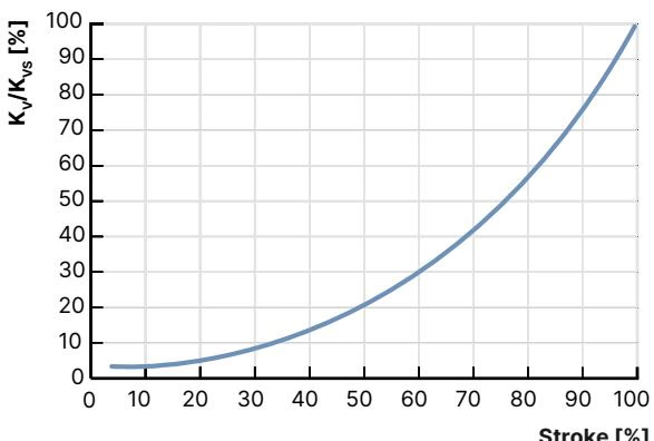
Type 2961 valves follow an equal percentage flow profile in compliance with DIN EN 60534-2-4. For seat sizes equal to or smaller than 10 mm, the minimum controlled flow value KvR is established at 10% of stroke to maintain tolerance compliance.
For article 20135264, the nominal stroke travel is 19 mm. The table below lists water Kv values [m³/h] across opening stroke increments from 5% to 100%:
| Parameter | Operating Value |
|---|---|
| Valve Pipe Size | DN 25 (NPS 1) |
| Seat Orifice Diameter | 10 mm |
| Handwheel Diameter | 45 mm (Size S) |
| Maximum Differential Pressure CF A (PTFE) | 25 bar(g) (Leakage Class VI) |
| Theoretical Rangeability | 50:1 |
| Stroke 5% | 0.10 m³/h |
| Stroke 10% | 0.12 m³/h |
| Stroke 20% | 0.15 m³/h |
| Stroke 30% | 0.19 m³/h |
| Stroke 40% | 0.30 m³/h |
| Stroke 50% | 0.46 m³/h |
| Stroke 60% | 0.67 m³/h |
| Stroke 70% | 1.0 m³/h |
| Stroke 80% | 1.5 m³/h |
| Stroke 90% | 2.1 m³/h |
| Stroke 100% (Kvs) | 2.8 m³/h |
The permissible operating pressure of the stainless steel valve body is determined by pressure derating curves conforming to DIN EN 12516-1 (PN 25 rating):
| Medium Temperature [°C] | Maximum Permissible Operating Pressure [bar] |
|---|---|
| -10 °C to +50 °C | 25.0 bar |
| +100 °C | 24.5 bar |
| +130 °C (PTFE seat limit) | 23.2 bar |
| +150 °C | 22.4 bar |
| +200 °C | 20.3 bar |
| +230 °C | 19.0 bar |
Temperature Limit for Soft Seat
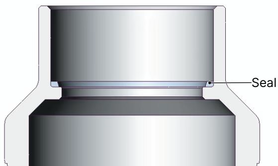
BURKERT 20135264 is fitted with a virgin PTFE seat seal, restricting continuous media temperature to a range of -10 °C to +130 °C. For processes exceeding +130 °C up to +230 °C, PEEK or metallic stainless steel seat trims are required.
Line Depressurization
Relieve all pipeline pressure and fully drain process lines before handling or installing the valve. Trapped pressurized media can cause severe physical injury.
To prevent thermal damage to the internal graphite seal, PTFE seat seal, and plastic actuator during pipe welding, the actuator must be disassembled from the body:
| Valve Body Nominal Diameter | Tightening Torque [Nm] | Tolerance [Nm] |
|---|---|---|
| DN 10 / DN 15 | 45 Nm | ±3 Nm |
| DN 20 | 50 Nm | ±3 Nm |
| DN 25 (Article 20135264) | 60 Nm | ±3 Nm |
| DN 32 / DN 40 | 65 Nm | ±3 Nm |
| DN 50 | 70 Nm | ±3 Nm |
| DN 65 | 100 Nm | ±3 Nm |
| DN 80 | 120 Nm | ±5 Nm |
| DN 100 | 150 Nm | ±5 Nm |
Pipeline Stress and Vibration Check
In systems subject to intense line vibration or sustained temperatures exceeding 140 °C, inspect the body-to-actuator joint torque periodically to prevent screw connection loosening.
Under regular industrial operation conforming to operating limits, the PPS manual actuator is maintenance-free. Perform a visual inspection of external surfaces and seal junctions at least once per year.
The bonnet housing includes an inspection relief bore located between the primary process seal and the actuator head. Periodically inspect this bore. Escaping medium from the relief bore signifies wear of the internal spindle packing gland V-rings.
| Fault Symptom | Probable Cause | Corrective Action |
|---|---|---|
| Valve does not seal tightly in closed position | Foreign particles trapped between plug seal and seat orifice | Clean internal seat cavity; install upstream pipeline strainer |
| PTFE seat seal worn or mechanically deformed | Replace the control plug / seat sealing member | |
| Reverse flow orientation | Reorient valve so flow enters beneath the seat (arrow on body) | |
| Operating pressure exceeds rating | Verify process pressure against PN25 nameplate ratings | |
| Fluid leaks from actuator relief bore | Spindle packing gland V-rings worn or degraded | Replace the spindle packing gland set using original spare kit |
Explore similar products in our catalog



