


PN25

BURKERT 324651 (Type 2100) is a pneumatically operated 2/2-way angle seat valve with G 2 threaded ports, normally closed CF A operation, stainless steel body, PTFE seat seal, and 10 bar operating pressure.
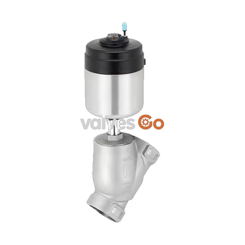
BURKERT 324651 (Type 2100) is a pneumatically operated 2/2-way angle seat valve engineered for decentralized process automation in demanding industrial fluid systems. Built with a cast CF3M stainless steel body featuring G 2 internal threaded connections (DN50), the valve is powered by a 90 mm (size N) single-acting pneumatic actuator. The valve operates under control function A (normally closed by spring force), utilizing an incoming media flow directed below the valve seat. Media sealing is provided by a virgin PTFE seat seal meeting DIN EN 12266-1 leakage rate A, backed by a self-adjusting PTFE V-ring spindle packing gland with integrated spring compensation. This configuration is rated for operating pressures up to 10.0 bar(g) and fluid temperatures ranging from -10 °C to +185 °C (derated up to +230 °C according to DIN EN 12516-1), delivering a water flow capacity of 55 m³/h ($K_v$). Both Clean-in-Place (CIP) and Steam-in-Place (SIP) sterilization cycles are supported.
| Parameter | Specification |
|---|---|
| Article Number | 324651 |
| Valve Type Family | Type 2100 ELEMENT |
| Nominal Diameter | DN 50 (NPS 2) |
| Port Connection | G 2 internal thread (DIN ISO 228-1) |
| Circuit Function | 2/2-way, Control Function A (normally closed by spring force) |
| Actuator Size | Ø 90 mm (size N) |
| Operating Pressure Range | 0.00 bar(g) to 10.00 bar(g) |
| Minimum Pilot Pressure | 5.0 bar(g) |
| Maximum Pilot Pressure | 10.0 bar(g) |
| Flow Coefficient ($K_v$) | 55 m³/h (water at +20 °C, 1 bar inlet pressure, free outlet) |
| Seat Leakage Rate | Leakage rate A according to DIN EN 12266-1 |
| Valve Body Material | Cast stainless steel CF3M (equivalent to 1.4404 / 316L) |
| Seat Seal Material | PTFE (Polytetrafluoroethylene) |
| Spindle Packing Gland | Self-adjusting PTFE V-rings with spring compensation |
| Medium Temperature Range | -10 °C to +185 °C (up to +230 °C with pressure derating) |
| Permissible Fluid Viscosity | Max. 600 mm²/s |
| Pilot Air Connection | Push-in connector for 6 mm external hose (G 1/8 option) |
| Pilot Air Media | Filtered compressed air, neutral gases |
| Degree of Protection | IP65 / IP67 according to EN 60529, NEMA Type 4X |
| Cleanability | CIP (Clean-in-Place) and SIP (Steam-in-Place) capable |
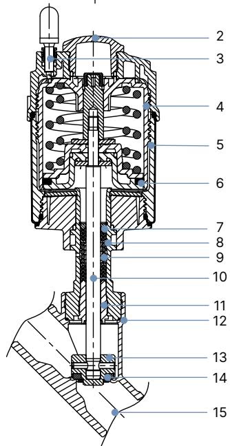
| Item | Component | Material |
|---|---|---|
| 1 | Ground terminal | Stainless steel 1.4301 / 1.4305 (ATEX variants only) |
| 2 | Optical position indicator | Polysulfone (PSU) |
| 3 | Pilot air ports | Polypropylene (PP) push-in connector (standard); G 1/8 stainless steel 1.4305 (option) |
| 4 | Actuator cover | Polyphenylene sulfide (PPS) |
| 5 | Actuator casing | Stainless steel 1.4561 (316Ti) |
| 6 | Piston seal | Fluoroelastomer (FKM) |
| 7 | Spring | Stainless steel 1.4310 |
| 8 | Pipe | Stainless steel 1.4401 (316) / 1.4404 (316L) |
| 9 | Packing gland | Filled PTFE V-rings with spring compensation |
| 10 | Spindle | Stainless steel 1.4401 (316) / 1.4404 (316L) |
| 11 | Spindle guide | Polyether ether ketone (PEEK) |
| 12 | Body seal | Graphite (PTFE optional) |
| 13 | Swivel plate | Stainless steel 1.4401 (316) / 1.4404 (316L) |
| 14 | Seat seal | PTFE (PEEK optional) |
| 15 | Valve body | Cast stainless steel CF3M |
Lubricant Compliance
Lubricants applied within the spindle packing gland and pneumatic actuator assembly are classified according to NSF H1 for incidental contact with food-processing media.
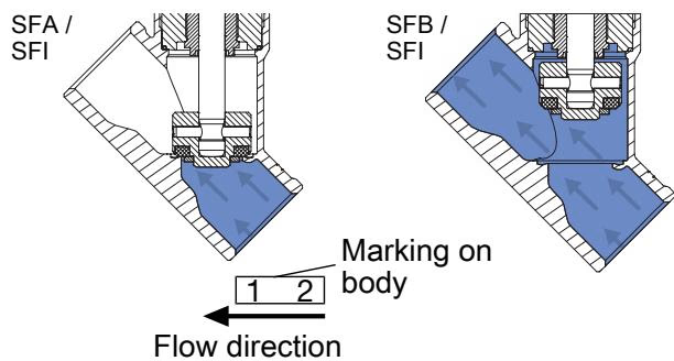
In control function A, the valve is maintained in the closed position by actuator spring force acting downwards on the swivel plate. Compressed pilot air supplied to pilot air port 1 acts on the lower surface of the actuator piston, compressing the internal springs and raising the spindle to open the seat. When pilot air is vented, the springs force the spindle and seat seal back onto the orifice seat.
Article 324651 is engineered specifically for media flow entering below the valve seat (flow to open). Because line pressure acts against the underside of the swivel plate, line pressure assists in opening the valve and prevents the onset of closing water hammer.
Liquid Media Operating Limit
Do not use valves configured with flow above the seat for liquid media. Rapid seat closure against moving liquid columns generates hydraulic pressure surges (water hammer) that can rupture pipework and valve bodies. Flow below the seat (as implemented on 324651) must always be selected for liquid service.
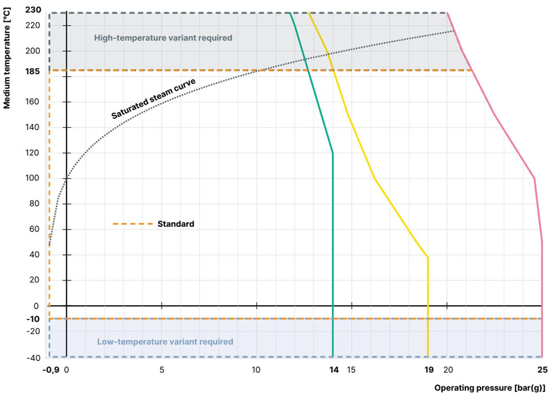
While article 324651 features a maximum mechanical pressure rating of 10.0 bar(g) for the DN50 size N actuator configuration, the allowable continuous operating pressure decreases at elevated medium temperatures in compliance with pressure-temperature ratings:
| Medium Temperature (°C) | Maximum Permissible Operating Pressure (bar) |
|---|---|
| -10 to +50 | 25.0 (limited to 10.0 bar by 324651 actuator/spring balance) |
| +100 | 24.5 (limited to 10.0 bar by 324651 actuator/spring balance) |
| +150 | 22.4 (limited to 10.0 bar by 324651 actuator/spring balance) |
| +185 | 20.8 (limited to 10.0 bar by 324651 actuator/spring balance) |
| +200 | 20.3 (limited to 10.0 bar by 324651 actuator/spring balance) |
| +230 | 19.0 (limited to 10.0 bar by 324651 actuator/spring balance) |
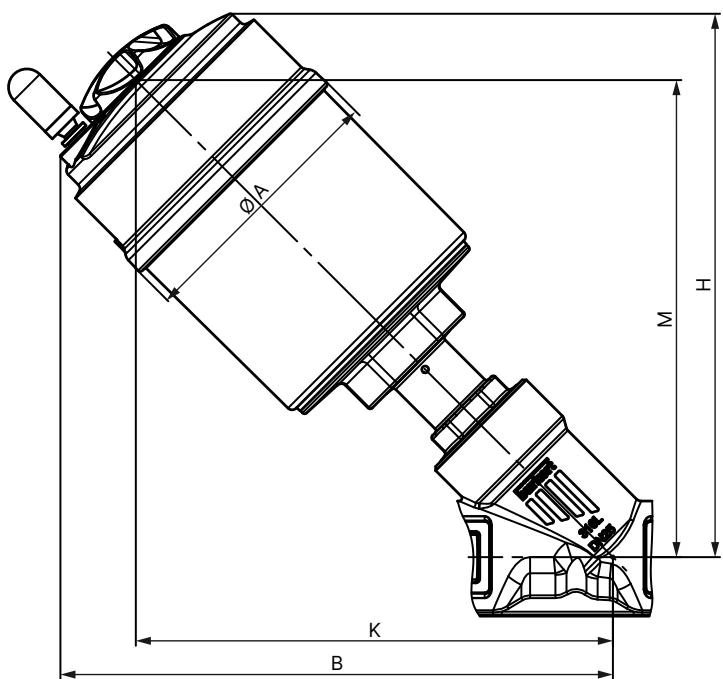
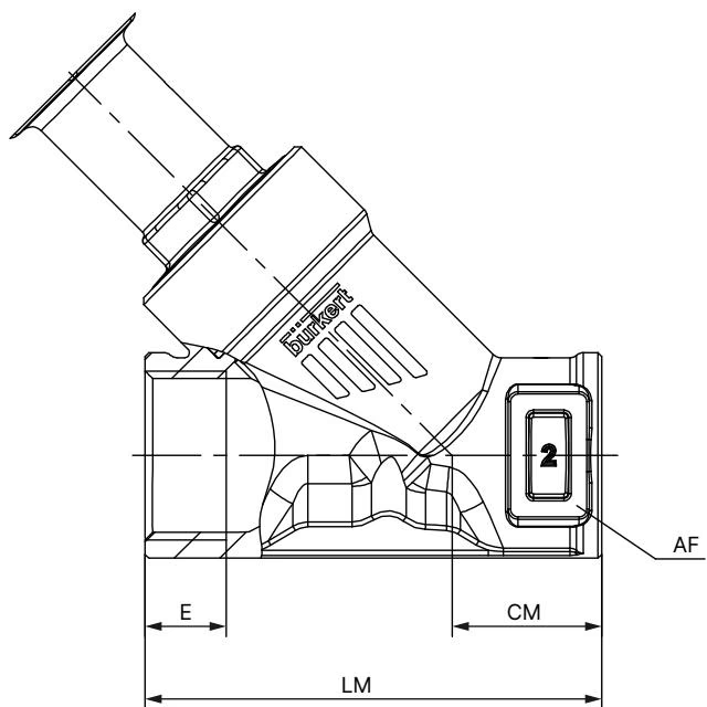
| Actuator Size | Ø A (mm) | B (mm) | H (mm) | K/M (mm) |
|---|---|---|---|---|
| 90 (N) | 120 | 262 | 261 | 236 |
Dimensions B, H, K, and M represent maximum outer envelope values and may be up to 6 mm less depending on process connection tolerances.
| Port Connection | DN | NPS | E (mm) | CM (mm) | LM (mm) | AF (Wrench Flat, mm) |
|---|---|---|---|---|---|---|
| G 2 | 50 | 2 | 24 | 45 | 150 | 70 |
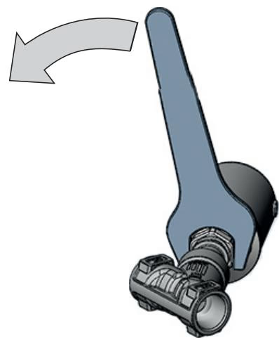
The valve may be installed in any physical mounting orientation, though an upright vertical position with the actuator facing upwards is preferred. Align pipeline flanges or threads without mechanical strain prior to final fastening.
When securing or reinstalling the actuator housing to the stainless steel CF3M valve body, observe the defined torque parameters:
| Nominal Diameter (DN) | Actuator Sizes | Tightening Torque (Nm) | Tolerance (Nm) |
|---|---|---|---|
| DN 15 | 40 (C), 50 (D), 63 (E) | 45 | +10 / -5 |
| DN 20 | 40 (C), 50 (D), 63 (E), 80 (F) | 50 | +10 / -5 |
| DN 25 | 50 (D), 63 (E), 80 (F) | 60 | +10 / -5 |
| DN 32 | 63 (E), 80 (F), 100 (G) | 65 | +10 / -5 |
| DN 40 | 63 (E), 80 (F), 100 (G), 125 (H) | 65 | +10 / -5 |
| DN 50 | 63 (E), 70 (M), 80 (F), 90 (N), 100 (G), 125 (H) | 70 | +10 / -5 |
| DN 65 | 80 (F), 100 (G), 125 (H) | 70 | +10 / -5 |
| DN 65 | 175 (K), 225 (L) | 100 | +10 / -5 |
| DN 80 | 125 (H), 130 (P) | 120 | +10 / -5 |
Pneumatic pilot ports can be positioned 360° to accommodate tight pipe routing:
Spring Hazard
The internal actuator chamber contains a heavily pre-compressed spring assembly. Never attempt to disassemble or unbolt the actuator housing.
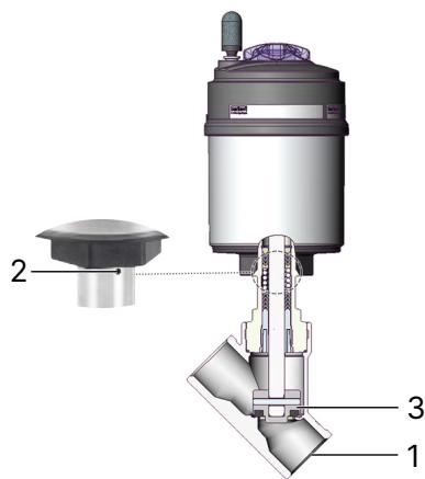
Conduct regular visual inspections of the three primary boundary zones:
| Inspection Zone | Observed Condition | Corrective Action |
|---|---|---|
| Media connectors (1) | Fluid seepage across pipeline thread joints | Re-seal or torque G 2 pipe connection threads |
| Relief bore (2) | Process media dripping from actuator weep hole | Replace the spindle packing gland kit or actuator assembly |
| Valve seat (3) | Downstream leakage while actuator is de-energized | Replace the swivel plate and PTFE seat seal disc |
| Problem | Probable Cause | Corrective Action |
|---|---|---|
| Actuator fails to open | Pilot air port reversed or de-pressurized | Connect pilot pressure line (min. 5.0 bar) to pilot air port 1 |
| Pilot air supply pressure below 5.0 bar(g) | Increase pilot supply pressure to 5.0–10.0 bar(g) | |
| Media line pressure exceeds 10.0 bar(g) | Reduce pipeline operating pressure to within rated limits | |
| Valve leaks across the seat | Debris entrapped between PTFE seal and seat orifice | Flush line; install upstream strainer with ≤ 1 mm mesh |
| Worn or scored PTFE seat seal disk | Replace swivel plate assembly | |
| Leakage at actuator relief bore | Worn V-ring packing gland seals | Replace spindle packing using socket wrench tool 683223 |
Type 2100 is engineered for direct mechanical and pneumatic coupling with Burkert ELEMENT automation modules without external pilot tubing:
Explore similar products in our catalog



