


PN25

BURKERT 338166 (Type 2100) is a pneumatically operated 2/2-way NC angle seat valve with DN 15 ASME BPE clamp connections, stainless steel body, PTFE seat seal, and PN25 pressure rating.
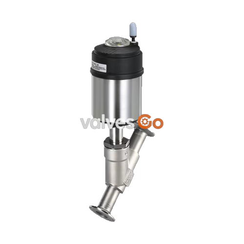
BURKERT 338166 (Type 2100) is a pneumatically operated 2/2-way angle seat valve belonging to the ELEMENT platform, engineered for hygienic and process industrial service. Configured under article number 338166, the assembly features a DN 15 nominal port size with ASME BPE clamp connections, an installation face-to-face length of 130 mm, an actuator size of 70 mm (size code M), and Control Function A (normally closed by internal spring force). Fluid enters below the seat (flow-to-open), eliminating hydraulic pressure surges when closing against liquid media.

The flow-optimized cast stainless steel body (CF3M) achieves a flow coefficient Kv of 1.6 m³/h with water. Sealing integrity at the seat is maintained by a virgin PTFE seal ring, meeting Leakage Class A per DIN EN 12266-1 under operating pressures up to 25 bar(g). The spindle is guided by PEEK bushings and sealed with a self-adjusting PTFE V-ring packing gland incorporating spring compensation, preventing stem leakage across repeated thermal cycles from -10 °C to +185 °C. The valve is CIP and SIP capable and complies with EC Regulation 1935/2004.
Type 2100 angle seat valves are built in multiple operating functions across single-acting and double-acting configurations:
Flow Direction and Water Hammer Restrictions
When using liquid media, fluid must always flow below the seat (flow to open). In the case of liquid mediums, flow above the seat generates severe hydraulic water hammer during closing, which can burst process pipelines, fittings, and the valve body. Never install valves with flow above the seat on liquid services.
Flow direction below the seat introduces line pressure beneath the swivel plate, assisting valve opening upon pilot actuation. Flow direction above the seat is reserved strictly for compressible gases and clean steam, where line pressure assists seat tightness in normally closed (CF A) configurations.
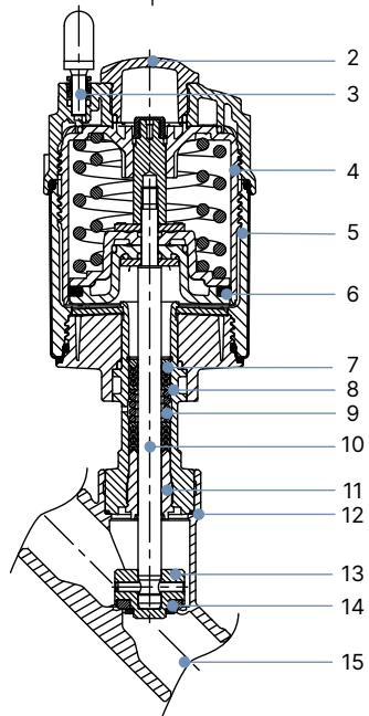
Wetted and structural components utilize corrosion-resistant metallurgy and engineering polymers. Factory lubricants applied to the packing gland and pneumatic actuator are certified according to NSF H1.
| Item | Component | Material Specification |
|---|---|---|
| 1 | Ground terminal | Stainless steel 1.4301 / 1.4305 (supplied for ATEX variants) |
| 2 | Optical position indicator | Polysulfone (PSU) |
| 3 | Pilot air ports | Polypropylene PP push-in connector (Standard); G 1/8" 1.4305 stainless steel on request |
| 4 | Actuator cover | Polyphenylene sulphide (PPS) |
| 5 | Actuator casing | Stainless steel 1.4561 (316Ti) |
| 6 | Piston seal | Fluoroelastomer (FKM) |
| 7 | Spring pack | Stainless steel 1.4310 |
| 8 | Actuator pipe | Stainless steel 1.4401 (316) / 1.4404 (316L) |
| 9 | Packing gland | PTFE V-rings (filled), spring-compensated |
| 10 | Spindle | Stainless steel 1.4401 (316) / 1.4404 (316L) |
| 11 | Spindle guide | Polyether ether ketone (PEEK) |
| 12 | Body seal | Graphite (PTFE optional) |
| 13 | Swivel plate | Stainless steel 1.4401 (316) / 1.4404 (316L) |
| 14 | Seat seal | Virgin PTFE (PEEK optional) |
| 15 | Valve body | Cast stainless steel CF3M (316L equivalent) |
Fluidic performance for welded and clamp connections complying with ASME BPE / DIN 11866 series C with media flowing below the seat:
| Nominal Diameter DN | NPS | Seat Size DN [mm] | Actuator Size Ø [mm] | Kv Water [m³/h] | Min. Pilot Pressure [bar(g)] | Max. Operating Pressure CFA PTFE [bar(g)] | Max. Operating Pressure CFA PEEK [bar(g)] | Max. Operating Pressure CFB PTFE [bar(g)] |
|---|---|---|---|---|---|---|---|---|
| 15 | 1/2" | 15 | 50 (D) | 1.6 | 5.2 | 25.0 | 25.0 | 25.0 |
| 15 | 1/2" | 15 | 70 (M) | 1.6 | 4.8 | 25.0 | 25.0 | 25.0 |
| 20 | 3/4" | 20 | 50 (D) | 8.4 | 5.2 | 16.0 | 13.5 | 25.0 |
| 20 | 3/4" | 20 | 70 (M) | 9.4 | 4.8 | 25.0 | 25.0 | 25.0 |
| 25 | 1" | 25 | 50 (D) | 13.0 | 5.2 | 9.0 | — | 25.0 |
| 25 | 1" | 25 | 70 (M) | 16.0 | 4.8 | 16.0 | 13.5 | 25.0 |
| 25 | 1" | 25 | 90 (N) | 16.0 | 5.0 | 25.0 | 25.0 | 25.0 |
| 40 | 1 1/2" | 40 | 70 (M) | 35.0 | 4.8 | 6.0 | — | 25.0 |
| 40 | 1 1/2" | 40 | 90 (N) | 38.0 | 5.0 | 16.0 | 13.5 | 25.0 |
| 40 | 1 1/2" | 40 | 130 (P) | 41.0 | 5.0 | 25.0 | 23.0 | 25.0 |
| 50 | 2" | 50 | 70 (M) | 49.0 | 4.8 | 4.0 | — | 16.0 |
| 50 | 2" | 50 | 90 (N) | 55.0 | 5.0 | 10.0 | 8.0 | 25.0 (20.0 *) |
| 50 | 2" | 50 | 130 (P) | 58.0 | 5.0 | 25.0 (20.0 *) | 23.0 (20.0 *) | 25.0 (20.0 *) |
| 65 | 2 1/2" | 65 | 90 (N) | 85.0 | 5.0 | 5.0 | — | 14.0 |
| 65 | 2 1/2" | 65 | 130 (P) | 85.0 | 5.6 | 16.0 (15.0 *) | 12.5 | 16.0 (15.0 *) |
| 80 | 3" | 65 | 90 (N) | 91.0 | 5.0 | 5.0 | — | 14.0 |
| 80 | 3" | 65 | 130 (P) | 91.0 | 5.6 | 16.0 (15.0 *) | 12.5 | 16.0 (15.0 *) |
| 80 | 3" | 80 | 130 (P) | 140.0 | 5.6 | 10.0 | 8.0 | 11.0 |
* Pressure reduction per Pressure Equipment Directive 2014/68/EU for compressible fluids of group 1 (dangerous gases and vapors).
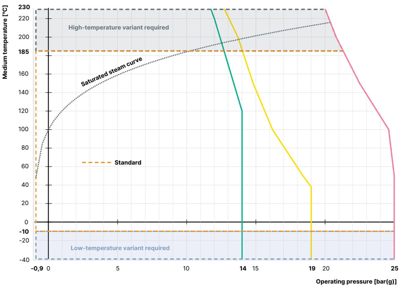
Maximum working pressure decreases at elevated medium temperatures according to international piping codes.
| Temperature [°C] | DIN EN 12516-1 / PN 25 [bar] | ASME B16.34 Cl. 150 [bar] | JIS B 2220 10K [bar] |
|---|---|---|---|
| -29 to +38 | 25.0 | 19.0 | 14.0 |
| -10 to +50 | 25.0 | 18.4 | 14.0 |
| 100 | 24.5 | 16.2 | 14.0 |
| 150 | 22.4 | 14.8 | 13.4 |
| 200 | 20.3 | 13.7 | 12.4 |
| 230 | 19.0 | 12.7 | 11.7 |
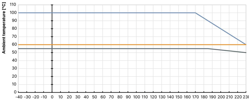
| Pilot Air Port Type | Medium Temperature Range (PTFE / PEEK) | Permissible Ambient Temperature Range |
|---|---|---|
| Push-in connector (external Ø 6 mm or 1/4") | -10 °C to +230 °C | -10 °C to +60 °C |
| Threaded metal bushing (G 1/8") | -10 °C to +230 °C | -10 °C to +100 °C |
| Mounted control head (Type 8691 / 8695 / 8690 / 8697) | -10 °C to +185 °C | -10 °C to +55 °C |
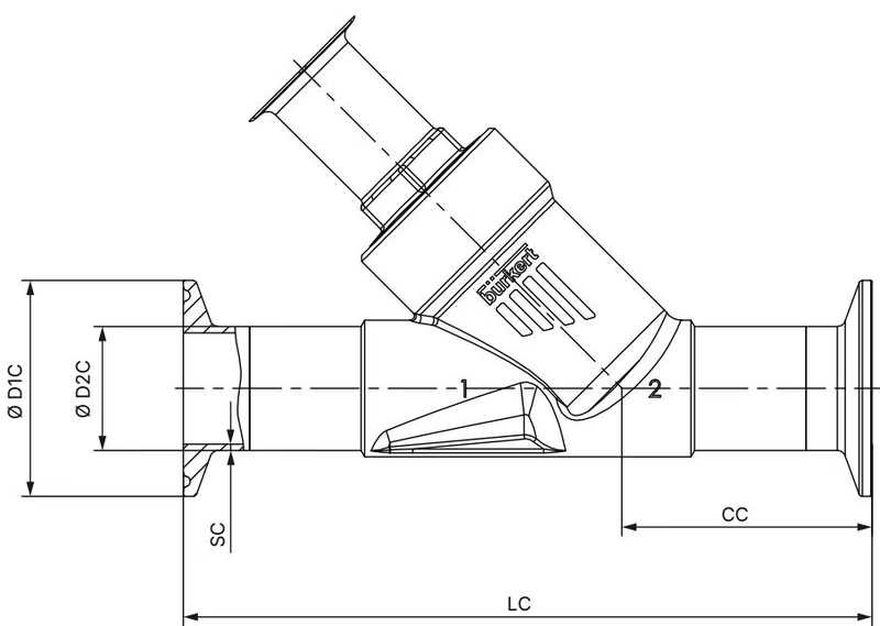
| NPS | DN | Overall Length LC [mm] | Body Center Height CC [mm] | Clamp Flange Ø D1 C [mm] | Tube OD Ø D2 C [mm] | Wall Thickness SC [mm] |
|---|---|---|---|---|---|---|
| 1/2" | 15 | 130 | 49.0 | 25.0 | 12.70 | 1.65 |
| 3/4" | 20 | 150 | 56.5 | 25.0 | 19.05 | 1.65 |
| 1" | 25 | 160 | 58.0 | 50.5 | 25.40 | 1.65 |
| 1 1/2" | 40 | 200 | 69.0 | 50.5 | 38.10 | 1.65 |
| 2" | 50 | 230 | 77.5 | 64.0 | 50.80 | 1.65 |
| Actuator Size Code | Actuator Housing Ø A [mm] | Total Height B [mm] | Axis Height H [mm] | Centerline Clearance K/M [mm] |
|---|---|---|---|---|
| 50 (D) | 64.5 | 166 | 163 | 147 |
| 70 (M) | 91.0 | 182 | 178 | 156 |
| 90 (N) | 120.0 | 229 | 228 | 203 |
| 130 (P) | 159.0 | 293 | 293 | 254 |
Dimensions B, H, K, and M represent maximum envelope values and may measure up to 6 mm less depending on the specific body port size and standard.
Pipe systems must be clean, free from welding slag or debris, and properly aligned before clamping. For gas installations certified to DIN EN 161, a dirt trap with a maximum mesh opening preventing the passage of a 1.0 mm mandrel must be installed upstream.
Pneumatic Actuation Required During Actuator Servicing
To avoid damaging the valve seat seal and spindle mechanism during actuator installation or removal, the valve must be held in the fully open position. For normally closed valves (Control Function A), apply 5.0 bar(g) of clean compressed air to pilot air port 1 before loosening or tightening the body connection.
When reinstalling the actuator onto the stainless steel valve body, inspect the body seal ring, apply food-grade thread paste (such as Klüber paste UH1 96-402), and tighten to the specified torque:
| Nominal Diameter DN | Actuator Sizes Covered | Specified Tightening Torque [Nm] | Permissible Tolerance [Nm] |
|---|---|---|---|
| 15 | 40 (C), 50 (D), 63 (E), 70 (M) | 45 | +10 / -5 |
| 20 | 40 (C), 50 (D), 63 (E), 70 (M), 80 (F) | 50 | +10 / -5 |
| 25 | 50 (D), 63 (E), 70 (M), 80 (F) | 60 | +10 / -5 |
| 32 | 63 (E), 70 (M), 80 (F), 90 (N), 100 (G) | 65 | +10 / -5 |
| 40 | 63 (E), 70 (M), 80 (F), 90 (N), 100 (G), 125 (H) | 65 | +10 / -5 |
| 50 | 63 (E), 70 (M), 80 (F), 90 (N), 100 (G), 125 (H) | 70 | +10 / -5 |
| 65 | 80 (F), 90 (N), 100 (G), 125 (H), 130 (P) | 70 | +10 / -5 |
| 65 | 175 (K), 225 (L) | 100 | +10 / -5 |
| 80 | 125 (H), 130 (P) | 120 | +10 / -5 |
| 100 | 125 (H), 175 (K), 225 (L) | 150 | +10 / -5 |
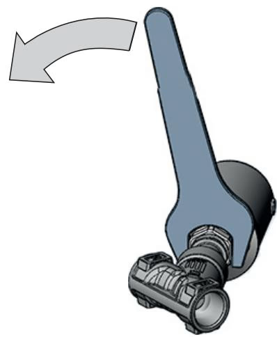
The pneumatic pilot ports can be positioned through 360° to accommodate tubing runs. Clamp the valve body firmly, pressurize pilot port 1 with 5 bar compressed air to open the valve orifice, and use an open-end wrench on the hexagon flat of the actuator drive connection. Hold the body connection stationary and rotate the actuator drive connection in the indicated tightening direction only to reach the desired alignment.
Pneumatic Connection Guidelines
Pneumatic pilot hoses require a 6 mm or 1/4" outer diameter. For push-in connections, a silencer is supplied loose to diminish exhaust velocity and noise; thread the silencer into free exhaust port 2. In corrosive or aggressive washdown areas, duct exhaust lines away into a neutral atmosphere.
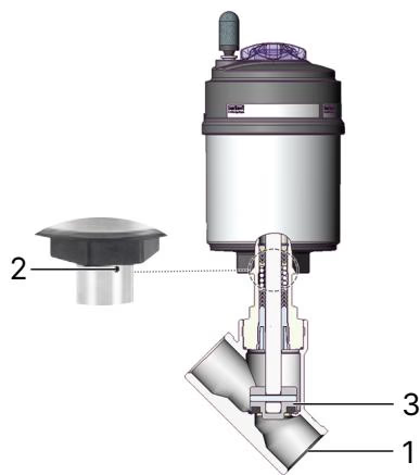
Regularly verify tight shut-off and external integrity during operation:
| Inspection Point | Observed Condition | Corrective Maintenance Action |
|---|---|---|
| Media connectors (1) | Flange clamp leaking | Re-align pipeline, verify gasket integrity, re-tighten clamp |
| Relief bore (2) | Process fluid weeping | Replace PTFE packing gland or complete actuator assembly |
| Swivel plate (3) | Internal seat bypass | Replace swivel plate assembly / seat seal ring |
Special socket wrenches are used to replace the stem packing gland cartridge without damaging internal guide surfaces:
| Fault Condition | Probable Root Cause | Corrective Action |
|---|---|---|
| Actuator fails to stroke | Pilot connections inverted | Connect pilot pressure line to port 1 for CF A and CF B valves |
| Pilot air pressure below rating | Verify pilot pressure satisfies minimum threshold (min. 4.8 bar for size 70) | |
| Line pressure exceeds limit | Check process operating pressure against nameplate maximum | |
| Reversed line installation | Verify medium flow arrow on valve casting matches pipeline flow direction | |
| Seat leakage in closed position | Pilot pressure low (CF B / CF I) | Raise pilot air supply to match pressure diagrams |
| Particulate under seat | Install upstream line strainer to block pipe scale | |
| Seat seal worn or damaged | Install replacement swivel plate kit | |
| Leakage through relief bore | Packing gland V-rings worn | Replace stem packing gland assembly using socket wrench tool |
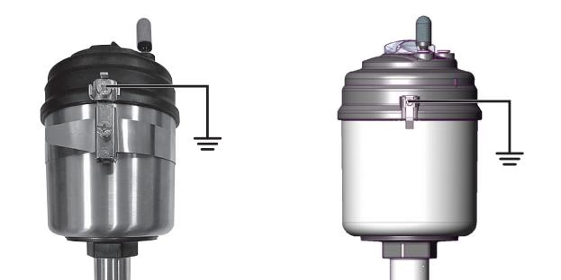
When ordered with ATEX / IECEx mechanical certification (codes PX51 / II 2G Ex h IIC T4…T2 Gb / II 2D Ex h IIIC T135 °C…T300 °C Db), mechanical equipment rules apply to prevent electrostatic ignition:
| Temperature Class | Maximum Permissible Surface Temperature | Permissible Ambient Temperature Range | Maximum Process Medium Temperature |
|---|---|---|---|
| T2 | +300 °C | -40 °C to +130 °C | +285 °C |
| T3 | +200 °C | -40 °C to +130 °C | +185 °C |
| T4 | +135 °C | -40 °C to +100 °C | +125 °C |
Grounding and Electrostatic Discharge
The valve body must have an equipotential bonding conductor connected to the plant piping system. All isolated conductive parts and the actuator must be grounded using the external grounding strap clamp and terminal lug. Clean the exterior housing using damp or antistatic cloths only.
Explore similar products in our catalog



