


PN25

BURKERT 345758 Type 2100 is a normally closed (CFA) pneumatic 2/2-way angle seat valve with DN15 NPT 1/2 ports, CF3M stainless steel body, PTFE seat seal, 5.3 m³/h Kv flow, and operating pressure up to 25 bar.
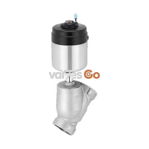
BURKERT 345758 (Type 2100) is a pneumatically operated 2/2-way angle seat valve engineered for decentralized process automation in hygienic, utility, and demanding industrial installations. The valve features a DN15 orifice, NPT 1/2 internal threaded port connections, and an integrated 50 mm (Size D) pneumatic piston actuator. Built with a cast CF3M stainless steel body, an internal self-adjusting PTFE V-ring packing gland, and a PTFE seat seal, the assembly provides tight shut-off according to DIN EN 12266-1 Leakage Rate A across operating pressures up to 25 bar(g) and fluid temperatures from -10 °C to +185 °C.

BURKERT 345758 operates under Control Function A (CFA), functioning as a normally closed (NC) 2/2-way valve. In the rest position without pilot air pressure, internal pre-tensioned stainless steel springs push the piston and valve spindle downward, pressing the PTFE swivel plate firmly against the valve seat.
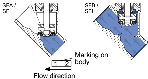
This specific model is configured for flow direction below the seat (closing against the incoming medium). Because the operating medium enters under the swivel plate, the line pressure assists in lifting the valve disc during actuation, eliminating severe fluid pressure shocks.
Flow Direction Specification
Flow direction below the seat is suitable for liquids, steam, and gases. Closing against the medium prevents line water hammer.
Operating Restriction
Do not use valves configured with flow direction above the seat for liquid media. Incompressible liquid flow over the seat causes severe hydraulic water hammer during closing, leading to ruptured piping or destroyed valve components.
The construction combines high-grade austenitic cast stainless steel CF3M for the body, forged 316/316L stainless steel internals, and an electropolished 1.4561 (316Ti) actuator body with an impact-resistant PPS actuator cover.
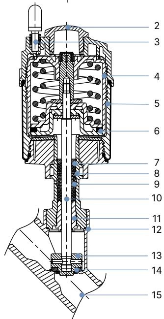
| Item No. | Element | Material |
|---|---|---|
| 1 | Ground terminal | Stainless steel 1.4301 / 1.4305 (only for ATEX variant) |
| 2 | Optical position indicator | Polysulfone (PSU) |
| 3 | Pilot air ports | Polypropylene (PP) push-in connector; stainless steel 1.4305 G 1/8" on request |
| 4 | Actuator cover | Polyphenylene sulphide (PPS) |
| 5 | Actuator casing | Stainless steel 1.4561 (316Ti) |
| 6 | Piston seal | Fluoroelastomer (FKM) |
| 7 | Spring assembly | Stainless steel 1.4310 |
| 8 | Actuator pipe | Stainless steel 1.4401 (316) / 1.4404 (316L) |
| 9 | Packing gland | PTFE V-rings (filled), with spring compensation |
| 10 | Valve spindle | Stainless steel 1.4401 (316) / 1.4404 (316L) |
| 11 | Spindle guide | Polyetheretherketone (PEEK) |
| 12 | Body seal | Graphite (PTFE optional) |
| 13 | Swivel plate | Stainless steel 1.4401 (316) / 1.4404 (316L) |
| 14 | Seat seal | PTFE (PEEK optional) |
| 15 | Valve body | Cast stainless steel CF3M |
The spindle seal utilizes self-adjusting PTFE V-rings backed by spring compensation, maintaining stem seal integrity without manual tightening. All internal lubricants for the packing gland and actuator are classified according to NSF H1.
For BURKERT 345758, the internal fluidic path is sized at DN15 with a 15 mm seat orifice, yielding a water flow factor (Kv) of 5.3 m³/h (measured with water at +20 °C and 1 bar pressure differential).
| Operational Parameter | Value |
|---|---|
| Nominal Diameter (Port Size) | DN 15 / NPS 1/2 |
| Port Connection | NPT 1/2 internal thread (ASME B1.20.1) |
| Actuator Size | Ø 50 mm (Size D) |
| Control Function | CFA (normally closed by spring force) |
| Flow Direction | Below seat (flow to open) |
| Water Flow Coefficient ($K_v$) | 5.3 m³/h |
| Minimum Pilot Pressure | 5.2 bar(g) |
| Maximum Pilot Pressure | 10.0 bar(g) |
| Maximum Operating Pressure (PTFE Seal) | 25.0 bar(g) |
| Maximum Operating Pressure (PEEK Seal) | 25.0 bar(g) |
| Seat Leakage Class | Rate A (DIN EN 12266-1) |
| Maximum Fluid Viscosity | 600 mm²/s |
BURKERT 345758 features an installation face-to-face body length (LM) of 65 mm. The actuator can be installed in any orientation, preferably upright.
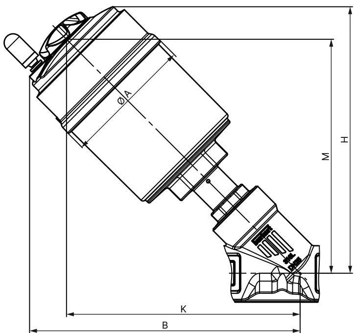
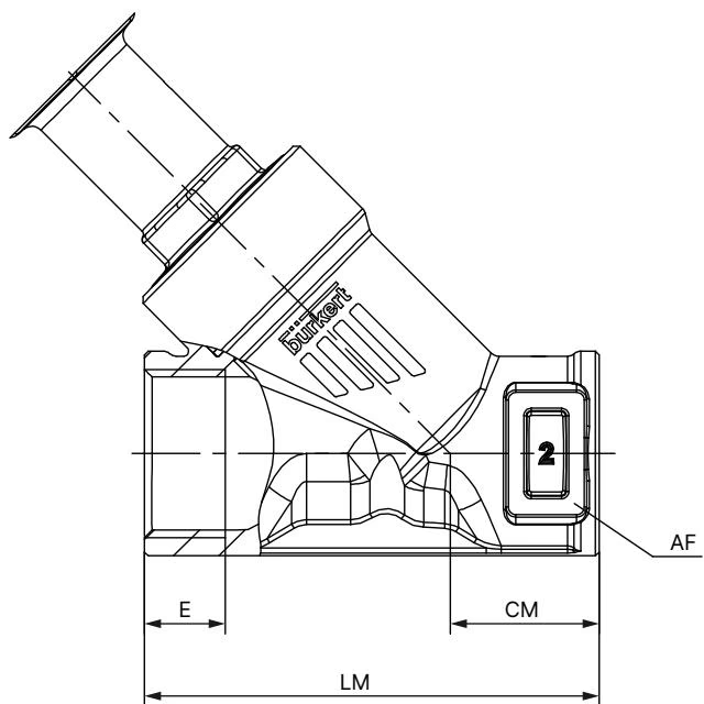
| DN | NPS | Actuator Size Ø | Ø A [mm] | B [mm] | H [mm] | K/M [mm] |
|---|---|---|---|---|---|---|
| 15 | 1/2 | 50 (D) | 64.5 | 166 | 163 | 147 |
| 15 | 1/2 | 70 (M) | 91.0 | 182 | 178 | 156 |
| 20 | 3/4 | 50 (D) | 64.5 | 174 | 171 | 155 |
| 20 | 3/4 | 70 (M) | 91.0 | 189 | 186 | 163 |
| 25 | 1 | 50 (D) | 64.5 | 175 | 173 | 156 |
| 25 | 1 | 70 (M) | 91.0 | 191 | 188 | 165 |
| 25 | 1 | 90 (N) | 120.0 | 229 | 228 | 203 |
| 32 | 1 1/4 | 70 (M) | 91.0 | 201 | 197 | 174 |
| 40 | 1 1/2 | 70 (M) | 91.0 | 204 | 201 | 178 |
| 50 | 2 | 70 (M) | 91.0 | 223 | 219 | 196 |
Note: Dimensions B, H, K, and M are maximum dimensions and may be up to 6 mm less depending on the specific connection standard.
| DN | NPS | E (G) [mm] | E (NPT) [mm] | E (RC) [mm] | CM [mm] | LM [mm] | AF [mm] |
|---|---|---|---|---|---|---|---|
| 8 | 1/4 | 14.0 | 10.0 | 9.7 | 24.0 | 75 | — |
| 10 | 3/8 | 12.0 | 10.3 | 10.1 | 24.0 | 65 | 27 |
| 15 | 1/2 | 14.0 | 13.7 | 13.2 | 24.0 | 65 | 27 |
| 20 | 3/4 | 16.0 | 14.0 | 14.5 | 27.0 | 75 | 34 |
| 25 | 1 | 18.0 | 16.8 | 16.8 | 29.5 | 90 | 41 |
| 32 | 1 1/4 | 16.0 | 17.3 | 19.1 | 36.0 | 110 | 50 |
| 40 | 1 1/2 | 18.0 | 17.3 | 19.1 | 35.0 | 120 | 55 |
| 50 | 2 | 24.0 | 17.6 | 23.4 | 45.0 | 150 | 70 |
| 65 | 2 1/2 | 26.0 | 23.7 | 26.7 | 57.0 | 185 | 85 |
| 80 | 3 | 28.0 | — | — | 71.0 | 220 | 100 |
Operating pressures must be derated when operating near maximum medium temperatures in accordance with DIN EN 12516-1 and ASME B16.34 standards.
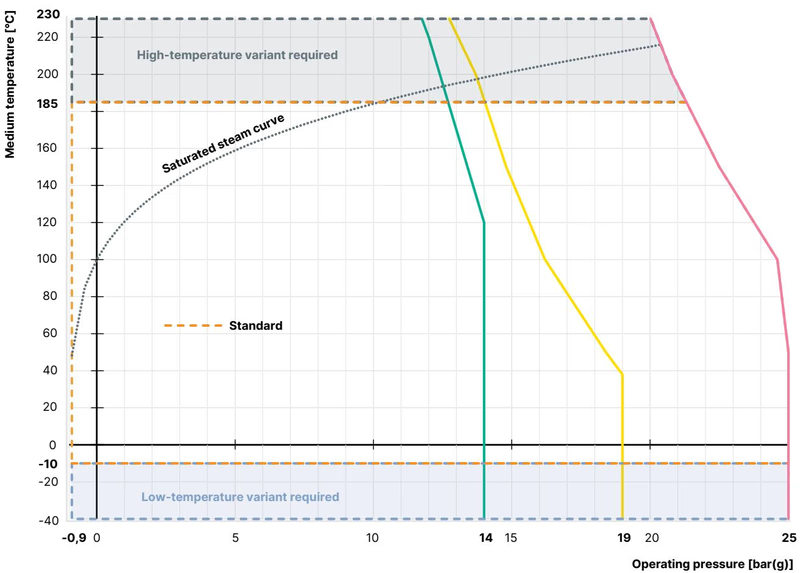
| Temperature [°C] | DIN EN 12516-1 (PN25) [bar] | ASME B16.34 Cl. 150 [bar] | JIS B 2220 10K [bar] |
|---|---|---|---|
| -29 to +38 | 25.0 | 19.0 | 14.0 |
| -10 to +50 | 25.0 | 18.4 | 14.0 |
| +100 | 24.5 | 16.2 | 14.0 |
| +150 | 22.4 | 14.8 | 13.4 |
| +185 | 21.0 | 14.1 | 12.8 |
| +200 | 20.3 | 13.7 | 12.4 |
| +230 | 19.0 | 12.7 | 11.7 |
For pilot air port connections, when using the standard push-in connector, the permitted ambient temperature range is -10 °C to +60 °C. With threaded bushings, the ambient limit reaches +100 °C.
BURKERT 345758 integrates directly into modular ELEMENT valve automation systems:
Observe pipeline alignment and flush all piping upstream to prevent foreign particles from damaging the seating surface.
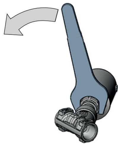
The pilot air connections can be rotated 360° to facilitate hose routing:
Avoid Joint Loosening
Rotating the actuator counter-clockwise risks loosening the central body thread, compromising sealing and allowing process media to escape under pressure.
When reattaching the pneumatic actuator to the valve body, lubricate the threads with Klüber paste UH1 96-402 and observe the specified torque values.
| Nominal Diameter | Actuator Size | Tightening Torque [Nm] | Tolerance [Nm] |
|---|---|---|---|
| DN 15 | 50 (D) | 45 | +10 / -5 |
| DN 20 | 50 (D), 70 (M) | 50 | +10 / -5 |
| DN 25 | 50 (D), 70 (M), 90 (N) | 60 | +10 / -5 |
| DN 32 | 70 (M), 90 (N), 130 (P) | 65 | +10 / -5 |
| DN 40 | 70 (M), 90 (N), 130 (P) | 65 | +10 / -5 |
| DN 50 | 70 (M), 90 (N), 130 (P) | 70 | +10 / -5 |
| DN 65 | 90 (N), 130 (P) | 70 | +10 / -5 |
| DN 80 | 130 (P) | 120 | +10 / -5 |
Regular visual inspection verifies external tightness and mechanical operating integrity.
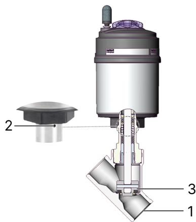
| Inspection Checkpoint | Observed Defect | Required Corrective Action |
|---|---|---|
| Media Connectors (1) | Medium leakage at pipeline joint | Reseal or repair pipe threading connections |
| Relief Bore (2) | Medium or pilot air leakage at relief port | Replace spindle packing gland or actuator assembly |
| Swivel Plate / Seat (3) | Downstream leakage through valve seat | Clean seat surface or replace internal swivel plate set |
| Fault Condition | Potential Root Cause | Corrective Procedure |
|---|---|---|
| Actuator does not switch | Pilot air port inverted | Connect pilot pressure correctly to port 1 for CFA |
| Pilot air pressure insufficient | Verify pilot air supply delivers minimum 5.2 bar(g) | |
| Operating medium pressure exceeds limit | Check that operating pressure is within 25 bar limit | |
| Medium flow reversed | Reinstall valve matching the flow direction arrow | |
| Valve does not seal tightly | Debris trapped between seal and seat | Dismantle, flush pipeline, and install upstream strainer |
| Worn or scored PTFE seat seal | Replace swivel plate assembly using factory kit | |
| Medium leaks at relief bore | Spindle packing gland seals worn | Replace packing gland using socket wrench 683221 |
Packing Gland Service Tool
Replacement of the internal spindle packing gland requires factory socket wrench Article No. 683221 (for 10 mm spindle, AF 19 mm, covering DN15 to DN50).
Explore similar products in our catalog



