


PN25

BURKERT 346227 (Type 2100) is a pneumatically operated 2/2-way angle seat valve with DN 15 clamp connection, PTFE seat seal, normally closed function, 5.3 m³/h flow rate, and 25 bar operating pressure.
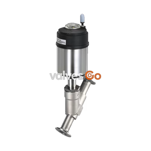
BURKERT 346227 (Type 2100) is a pneumatically operated 2/2-way angle seat valve engineered for decentralized process automation in hygienic, chemical, and demanding utility duties. The valve features a DN 15 investment-cast CF3M stainless steel body with a clamp process connection according to DIN 32676 series B for ISO 4200 pipelines. Operating under control function A (normally closed by spring force), the valve routes fluid below the seat, eliminating hydraulic pressure surges and water hammer in liquid duties while maintaining an operating pressure rating of 25 bar(g) and a flow coefficient Kv of 5.3 m³/h.
Built on the ELEMENT platform, article 346227 integrates a Ø 50 mm (size D) pneumatic actuator featuring a polyphenylene sulphide (PPS) cover, an electropolished 1.4561 (316Ti) casing, and internal pilot air routing. Dynamic stem sealing is maintained by a self-adjusting PTFE V-ring packing gland with spring compensation, backed by an inspection relief bore. All wetted metallic and polymer components satisfy European Regulation (EC) No 1935/2004 for food contact, and the assembly supports full Clean-in-Place (CIP) and Steam-in-Place (SIP) sterilization routines.
| Specification Parameter | Value / Engineering Classification |
|---|---|
| Article Number | 346227 |
| Valve Type | 2100 (ELEMENT on/off valve series) |
| Valve Construction | Complete pre-assembled valve assembly |
| Number of Ports / Positions | 2 ports / 2 positions (2/2-way) |
| Control Function | CF A: Normally closed by spring force |
| Flow Direction | Flow below the seat (flow to open) |
| Nominal Diameter (DN) | DN 15 (Seat diameter: 15 mm) |
| Flow Coefficient Kv (Water, +20 °C) | 5.3 m³/h |
| Process Connection | Clamp DIN 32676 series B (Pipe standard: ISO 4200 / DIN EN ISO 1127) |
| Clamp Flange Outer Diameter | 50.5 mm |
| Pipe Interface Dimensions | 21.3 mm OD × 1.6 mm wall thickness (ID: 18.1 mm) |
| Face-to-Face Length (LC) | 156 mm |
| Operating Pressure Range | 0 bar(g) to 25 bar(g) |
| Nominal Pressure Class | PN 25 (DIN EN 1333) / Class 150 (ASME B16.34) |
| Pilot Pressure Range | 5.2 bar(g) to 10 bar(g) (minimum pilot pressure: 5.2 bar) |
| Control Medium | Filtered compressed air, neutral gases |
| Pilot Air Port | Push-in connector Ø 6 mm (Interface ELEMENT) |
| Seat Leakage Class | Leakage rate A according to DIN EN 12266-1 (Air test medium) |
| Operating Media | Steam, water, neutral gases, alcohols, oils, fuels, hydraulic fluids, alkalis, saline solutions, organic solvents |
| Dynamic Viscosity Limit | Maximum 600 mm²/s |
| Medium Temperature Range | -10 °C to +185 °C |
| Ambient Temperature Range | -10 °C to +100 °C (-10 °C to +60 °C with push-in pilot air connectors) |
| Housing Enclosure Rating | IP65 / IP67 according to EN 60529, NEMA Type 4X |
| Cleanability Compliance | CIP capable, SIP capable |
| Hygienic Compliance | Regulation (EC) 1935/2004 compliant wetted materials |
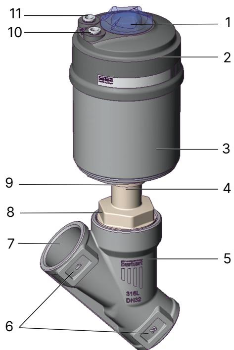
BURKERT 346227 operates under Control Function A (normally closed, NC). In the unpressurized rest state, internal pre-tensioned springs exert downward force on the actuator piston. This force transfers through the 1.4401/1.4404 stainless steel spindle to press the swivel plate with its PTFE seal against the valve seat.
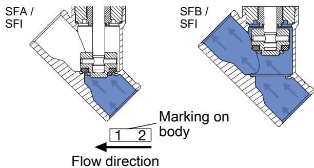
When pilot air at a minimum pressure of 5.2 bar(g) enters pilot air port 1, it acts on the lower chamber of the actuator piston, overcoming the mechanical spring pack and retracting the spindle upward to open the valve orifice. Because fluid enters under the seat, operating line pressure assists the opening movement. When pilot air exhausts through port 1, spring force returns the swivel plate to the closed seat position against the oncoming flow.
Flow Direction Restrictions
Do not use valves configured with flow above the seat on liquid media. Rapid closure with flow above the seat creates severe hydraulic pressure shock (water hammer) that damages pipework and valve internals. BURKERT 346227 utilizes flow below the seat, preventing water hammer across liquid, steam, and gas applications.
All components are selected for resistance to aggressive chemical washdowns, high operating temperatures, and steam sterilization. Lubricants applied to the packing gland and actuator mechanism are rated NSF H1 for food and beverage safety.
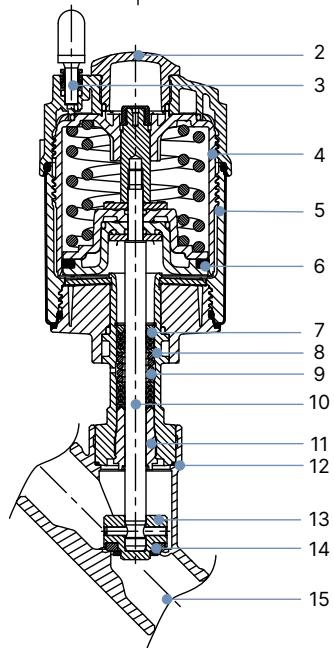
| Item No. | Component Part | Material Specification |
|---|---|---|
| 1 | Ground terminal | Stainless steel 1.4301 / 1.4305 (supplied with ATEX mechanical configurations) |
| 2 | Optical position indicator | Polysulfone (PSU) transparent cap |
| 3 | Pilot air ports | Polypropylene (PP) push-in connectors (Standard) / Thread G 1/8" (1.4305 optional) |
| 4 | Actuator cover | Polyphenylene sulphide (PPS) |
| 5 | Actuator casing | Stainless steel 1.4561 (316Ti) |
| 6 | Piston seal | Fluoroelastomer (FKM) |
| 7 | Actuator springs | Stainless steel 1.4310 |
| 8 | Guide pipe | Stainless steel 1.4401 (316) / 1.4404 (316L) |
| 9 | Packing gland | Self-adjusting filled PTFE V-rings with Belleville spring washer compensation |
| 10 | Valve spindle | Stainless steel 1.4401 (316) / 1.4404 (316L) |
| 11 | Spindle guide bushing | Polyetheretherketone (PEEK) |
| 12 | Body seal | Graphite (PTFE optional) |
| 13 | Swivel plate | Stainless steel 1.4401 (316) / 1.4404 (316L) |
| 14 | Seat seal | Virgin PTFE (Polytetrafluoroethylene) |
| 15 | Valve body | Investment cast stainless steel CF3M (equivalent to 1.4409 / AISI 316L) |
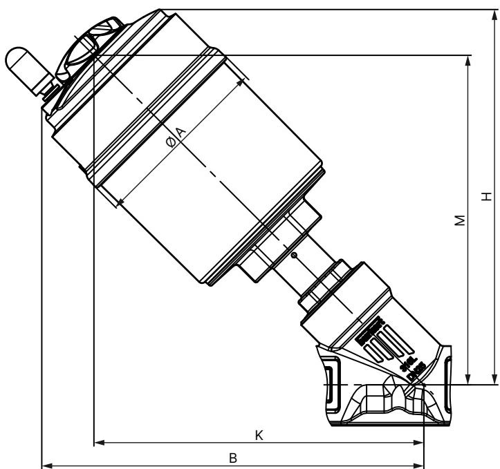
The Ø 50 mm actuator (size D) on BURKERT 346227 has an overall envelope diameter ∅A of 64.5 mm. The valve body features a face-to-face length of 156 mm with sanitary clamp end fittings matching DIN 32676 series B.
| Nominal Diameter | Actuator Size | Actuator Outer ∅ A [mm] | Dimension B [mm] | Dimension H [mm] | Dimension K/M [mm] |
|---|---|---|---|---|---|
| DN 15 (1/2") | 50 mm (D) | 64.5 | 166 | 163 | 147 |
| DN 15 with Type 8690 / 8697 | 50 mm (D) | 64.5 | 226 | 226 | - |
| DN 15 with Type 8691 / 8695 | 50 mm (D) | 64.5 | 239 | 239 | - |
Note: Dimensions B, H, K, and M represent maximum boundary clearances and may vary by up to 6 mm depending on connection tolerance.
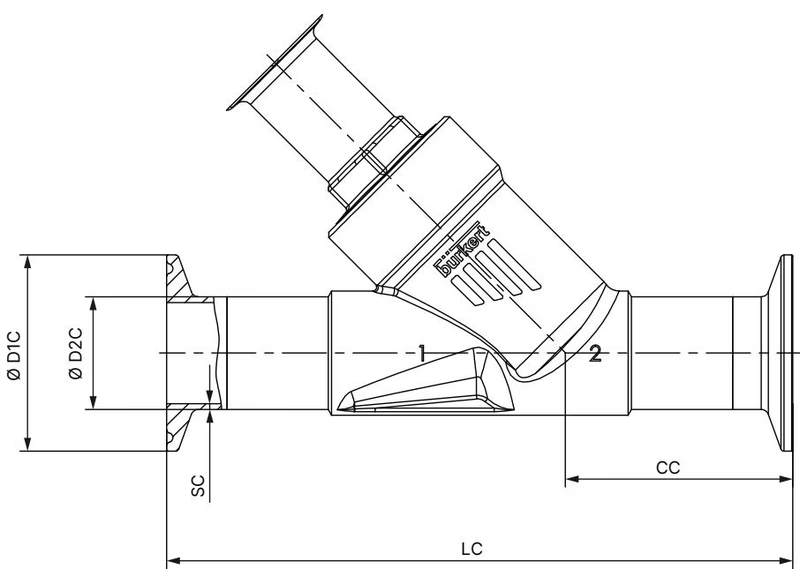
| Nominal Diameter (DN) | Pipe Standard | Installation Length LC [mm] | Centerline Height CC [mm] | Clamp Flange ∅ D1 C [mm] | Pipe Outer ∅ D2 C [mm] | Wall Thickness SC [mm] |
|---|---|---|---|---|---|---|
| DN 15 | ISO 4200 / DIN EN ISO 1127 | 156 | 49.0 | 50.5 | 21.3 | 1.6 |
BURKERT 346227 provides a flow coefficient Kv of 5.3 m³/h with water at +20 °C under 1 bar differential pressure. The maximum permissible operating pressure of 25 bar(g) is maintained across the entire standard temperature envelope when paired with a minimum control air supply of 5.2 bar(g).
| Medium Temperature [°C] | Maximum Permissible Operating Pressure [bar(g)] |
|---|---|
| -10 °C to +50 °C | 25.0 |
| +100 °C | 24.5 |
| +150 °C | 22.4 |
| +185 °C | 20.8 |
| +200 °C | 20.3 |
| +230 °C | 19.0 |
BURKERT 346227 supports modular field integration with dedicated ELEMENT automation units to form an automated valve system (Type 8801-YE).
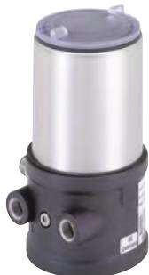
Before piping installation, flush lines thoroughly to clear welding slag, swarf, and debris. Mount the valve preferably with the actuator upright, observing the directional flow arrow cast into the CF3M valve body.
Actuator Rotation
The actuator connection can be rotated 360° to position pilot ports conveniently without altering piping alignments.
When reinstalling the actuator onto the valve body after maintenance or welding, apply food-grade lubricant (such as Klüberpaste UH1 96-402) to the threads, verify the condition of the body seal ring, open the valve pneumatically, and tighten to specification:
| Nominal Diameter (DN) | Actuator Diameter Size | Tightening Torque [Nm] | Tolerance [Nm] |
|---|---|---|---|
| DN 15 | 40 mm (C), 50 mm (D), 63 mm (E) | 45 | +10 / -5 |
| DN 20 | 40 mm (C), 50 mm (D), 63 mm (E), 80 mm (F) | 50 | +10 / -5 |
| DN 25 | 50 mm (D), 63 mm (E), 80 mm (F) | 60 | +10 / -5 |
| DN 32 | 63 mm (E), 80 mm (F), 100 mm (G) | 65 | +10 / -5 |
| DN 40 | 63 mm (E), 80 mm (F), 100 mm (G), 125 mm (H) | 65 | +10 / -5 |
| DN 50 | 70 mm (M), 90 mm (N), 100 mm (G), 125 mm (H) | 70 | +10 / -5 |
| DN 65 | 80 mm (F), 100 mm (G), 125 mm (H) | 70 | +10 / -5 |
| DN 80 | 125 mm (H), 130 mm (P) | 120 | +10 / -5 |
| DN 100 | 125 mm (H), 175 mm (K), 225 mm (L) | 150 | +10 / -5 |
Periodic maintenance involves regular visual inspection for external leakage across the process clamp joints, the packing gland relief bore, and the valve seat.
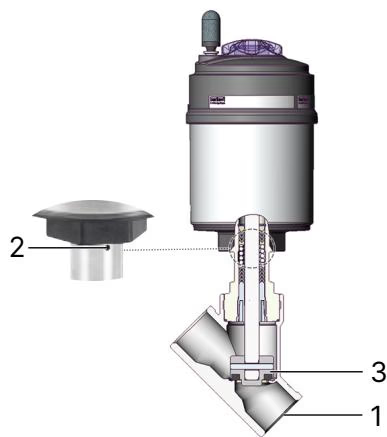
| Inspection Point | Observed Condition | Corrective Maintenance Action |
|---|---|---|
| Media Connection (1) | Leakage at sanitary clamp joint | Check and replace clamp gasket; re-torque clamp union |
| Relief Bore (2) | Process fluid weeping from actuator base | Replace stem packing gland assembly or actuator cartridge |
| Valve Seat (3) | Internal leakage through closed valve | Inspect seat orifice for debris; replace worn PTFE swivel plate |
| Fault Symptom | Root Cause | Corrective Action |
|---|---|---|
| Actuator fails to stroke | Pilot pressure below 5.2 bar threshold | Increase pilot air line pressure to 5.2–10.0 bar range |
| Pilot air line connected to wrong port | Connect control line to pilot air port 1 | |
| Operating medium pressure exceeds 25 bar | Verify process pressure conforms to nameplate limits | |
| Valve leaks across the seat | Debris lodged between PTFE seal and seat | Dismantle, flush line, and install upstream strainer |
| Worn or deformed PTFE seat seal | Replace swivel plate assembly | |
| Reverse flow orientation | Verify process flow enters below the seat | |
| Fluid leaks from relief bore | Worn V-ring spindle packing seal pack | Replace packing gland using installation tool (article 683221) |
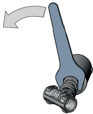
To overhaul the stem seal cartridge without damaging the guide threads, use the dedicated Bürkert packing gland socket wrench:
BURKERT 346227 complies with Pressure Equipment Directive (PED) 2014/68/EU and Machinery Directive 2006/42/EC. For installations in hazardous environments under optional ATEX/IECEx code PX51 (EPS 18 ATEX 2 008 X / IECEx EPS 18.0007X, Ex h IIC T4…T2 Gb / Ex h IIIC T135 °C…T300 °C Db), mechanical ground bonding must be installed.
Electrostatic Discharge Hazard in Ex Areas
Frictional cleaning on non-metallic surfaces can accumulate electrostatic charges. Clean external actuator surfaces only with a damp or anti-static cloth. Electrically bond the stainless steel valve body to pipeline ground using a conductive strap, and connect exposed metallic actuator housings to plant potential equalization via the ground terminal.
Explore similar products in our catalog



