


PN25

BURKERT 360873 (Type 2100) is a pneumatically operated 2/2-way NC angle seat valve with DN 32 weld ends, stainless steel body, PTFE seat seal, and flow below seat for steam, liquids, and gases up to 8.5 bar.
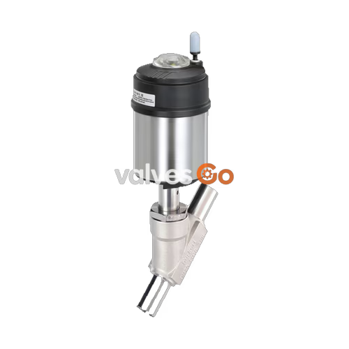
BURKERT 360873 Type 2100 is a pneumatically operated 2/2-way angle seat valve designed for decentralized process automation. Built with a cast stainless steel CF3M valve body and a 70 mm (Size M) ELEMENT pneumatic actuator, this configuration features DN 32 welded ports sized 42.4 × 2.0 mm according to ISO 4200, DIN EN ISO 1127, and DIN 11866 Series B standards. Operating under Control Function A (normally closed by spring force), the valve directs flow below the seat, preventing water hammer when handling steam, gases, and liquid process media up to 8.5 bar(g). The internal flow-optimized seat achieves a water flow coefficient Kv of 30 m³/h, combining high volumetric flow capacity with a tight shut-off classification conforming to DIN EN 12266-1 Leakage rate A.

Equipped with a self-adjusting PTFE V-ring packing gland with spring compensation, BURKERT 360873 ensures long service life and high external seal integrity across operating temperatures from -10 °C to +185 °C. The valve assembly is fully CIP and SIP capable, utilizing lubricants categorized under NSF H1 and wetted materials compliant with Regulation (EC) 1935/2004 and FDA regulations. Integrated pilot air channels in the ELEMENT design enable direct mounting of control heads and position indicators without external tubing, maintaining protection ratings of IP65/67 and NEMA Type 4X in corrosive or wash-down operating environments.
BURKERT 360873 utilizes a pneumatic piston actuator directly coupled to a stainless steel valve spindle. In rest position (unpressurized), internal pre-tensioned springs force the spindle and stainless steel swivel plate downward against the valve seat, sealing the flow path. Pressurizing pilot air port 1 with clean compressed air (minimum 4.8 bar(g), maximum 10.0 bar(g)) lifts the actuator piston against the spring force, retracting the PTFE swivel disc away from the seat to establish full flow.
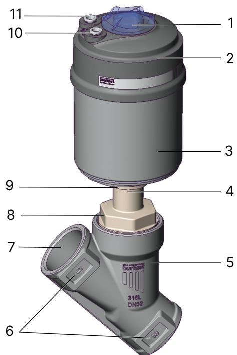
| Item | Description | Function in Operation |
|---|---|---|
| 1 | Transparent cap | Visual position confirmation; protective closure |
| 2 | Actuator cover | Polyphenylene sulphide (PPS) top enclosure housing pilot air channel |
| 3 | Actuator housing | Stainless steel 1.4561 (316Ti) cylinder containing the piston assembly |
| 4 | Relief bore | Atmospheric detection port monitoring packing gland integrity |
| 5 | Valve body | Investment cast stainless steel CF3M angle seat body with weld ends |
| 6 | Flow marking | Cast directional indicator for flow below seat (closing against media) |
| 7 | Port connection | DN 32 welding stubs (42.4 mm OD × 2.0 mm wall thickness) |
| 8 | Body connection | Threaded union interface joining actuator neck to valve body |
| 9 | Actuator connection | Hexagonal interface allowing 360° rotational positioning |
| 10 | Pilot air port 1 | Operating supply port: pressurize to open (Control Function A) |
| 11 | Pilot air port 2 | Atmospheric vent fitted with silencer or return line connector |
BURKERT 360873 operates exclusively with media flow below the valve seat (flow to open). When process media enters under the swivel disc, line pressure assists in opening the valve disc once pilot pressure is applied, effectively eliminating hydrodynamic shock and water hammer commonly encountered when shutting off liquid lines.
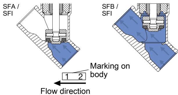
Operating Safety and Media Restrictions
BURKERT process valves configured for flow above the seat must never be used for liquid media due to severe risks of pipe rupture from liquid water hammer. BURKERT 360873 is engineered for flow below the seat, making it fully approved for liquid media, steam, and neutral gases.
All wetted and non-wetted materials are selected for chemical resistance and thermal cycling performance. The valve body is precision-cast in CF3M (a low-carbon austenitic stainless steel), while internal trim components are machined from 1.4401 (316) and 1.4404 (316L). The spindle gland system uses spring-loaded chevron PTFE V-rings that automatically compensate for packing wear over extended operating duty cycles.
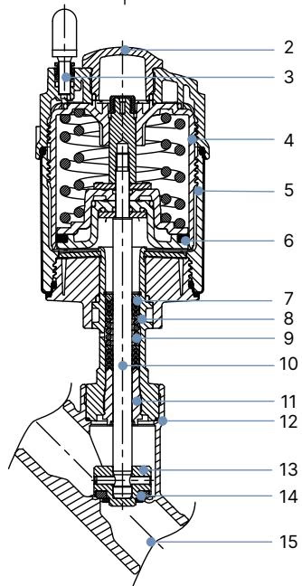
| No. | Element | Material Standard |
|---|---|---|
| 1 | Ground terminal | Stainless steel 1.4301 / 1.4305 (included for ATEX variants) |
| 2 | Optical position indicator | Polysulfone (PSU) |
| 3 | Pilot air ports | Polypropylene (PP) push-in connector standard (G 1/8" 1.4305 optional) |
| 4 | Actuator cover | Polyphenylene sulphide (PPS) |
| 5 | Actuator casing | Stainless steel 1.4561 (316Ti) |
| 6 | Piston seal | Fluorocarbon elastomer (FKM) |
| 7 | Actuator springs | Stainless steel 1.4310 |
| 8 | Spindle protection pipe | Stainless steel 1.4401 (316) / 1.4404 (316L) |
| 9 | Packing gland | PTFE V-rings (filled), spring-compensated |
| 10 | Valve spindle | Stainless steel 1.4401 (316) / 1.4404 (316L) |
| 11 | Spindle guide bushing | Polyetheretherketone (PEEK) |
| 12 | Body seal | Graphite (PTFE available as option) |
| 13 | Swivel plate | Stainless steel 1.4401 (316) / 1.4404 (316L) |
| 14 | Seat seal | Virgin PTFE |
| 15 | Valve body | Stainless steel CF3M |
Food Contact and Regulatory Compliance
Lubricants utilized in the packing gland and pneumatic cylinder comply with NSF H1 food-grade standards. According to the manufacturer declaration, all wetted components in BURKERT 360873 satisfy European Regulation (EC) 1935/2004 and FDA 21 CFR food contact regulations.
BURKERT 360873 combines an actuator size of Ø 70 mm (M) with a DN 32 welded angle-seat body. Port connections adhere to DIN EN ISO 1127 / ISO 4200 / DIN 11866 Series B welding specifications.
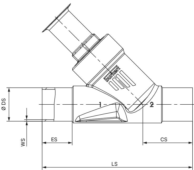
| Actuator Size | Ø A [mm] | B [mm] | H [mm] | K/M [mm] |
|---|---|---|---|---|
| 50 (D) | 64.5 | 175 | 173 | 156 |
| 70 (M) (Model 360873) | 91.0 | 201 | 197 | 174 |
| 90 (N) | 120.0 | 243 | 242 | 217 |
| 130 (P) | 159.0 | 293 | 293 | 254 |
Note: Dimensions B, H, K, and M represent maximum outer dimensions and can decrease by up to 6 mm based on specific body tolerance variations.
| Nominal Diameter | ES [mm] | CS [mm] | LS (Face-to-Face) [mm] | Ø DS (Outer Tube) [mm] | WS (Wall Thickness) [mm] |
|---|---|---|---|---|---|
| DN 15 | 19 | 34 | 100 | 21.3 | 1.6 |
| DN 20 | 20 | 39 | 115 | 26.9 | 1.6 |
| DN 25 | 26 | 43 | 130 | 33.7 | 2.0 |
| DN 32 (Model 360873) | 26 | 45 | 145 | 42.4 | 2.0 |
| DN 40 | 26 | 49 | 160 | 48.3 | 2.0 |
| DN 50 | 26 | 50 | 175 | 60.3 | 2.0 |
| DN 65 | 26 | 50 | 210 | 76.1 | 2.3 |
| DN 80 | 26 | 88.5 | 266 | 88.9 | 2.3 |
In this configuration (DN 32 seat size 32 mm with Actuator Size 70 mm M), BURKERT 360873 delivers precise shut-off capability against differential pressures up to 8.5 bar(g). Minimum pilot control pressure is set at 4.8 bar(g), and maximum permissible pilot pressure is 10.0 bar(g).
| Port Connection Pipe Ø [mm] | DN | Actuator Size Ø [mm] | Kv Value (Water) [m³/h] | Min. Pilot Pressure [bar(g)] | Max. Operating Pressure (PTFE) [bar(g)] | Article Number |
|---|---|---|---|---|---|---|
| 21.3 × 1.6 | DN 15 | 50 (D) | 2.6 | 5.2 | 25.0 | 187065 |
| 21.3 × 1.6 | DN 15 | 70 (M) | 2.6 | 5.0 | 25.0 | 188680 |
| 26.9 × 1.6 | DN 20 | 50 (D) | 10.0 | 5.2 | 16.0 | 210399 |
| 26.9 × 1.6 | DN 20 | 70 (M) | 11.0 | 5.0 | 25.0 | 188681 |
| 33.7 × 2.0 | DN 25 | 50 (D) | 15.0 | 5.2 | 9.0 | 235519 |
| 33.7 × 2.0 | DN 25 | 70 (M) | 20.0 | 5.0 | 16.0 | 188682 |
| 42.4 × 2.0 | DN 32 | 70 (M) | 30.0 | 4.8 | 8.5 | 360873 / 188683 |
| 42.4 × 2.0 | DN 32 | 90 (N) | 28.0 | 5.0 | 25.0 | 188684 |
| 48.3 × 2.0 | DN 40 | 70 (M) | 40.0 | 4.8 | 6.0 | 188685 |
| 48.3 × 2.0 | DN 40 | 90 (N) | 44.0 | 5.0 | 16.0 | 188686 |
| 60.3 × 2.0 | DN 50 | 90 (N) | 55.0 | 5.0 | 10.0 | 283500 |
| 60.3 × 2.0 | DN 50 | 130 (P) | 60.0 | 5.0 | 25.0 (20.0 Group 1) | 283501 |
Operating pressure limits are constrained by standard thermodynamic curves and material strength derating per DIN EN 12516-1 (PN 25) and ASME B16.34 Class 150.
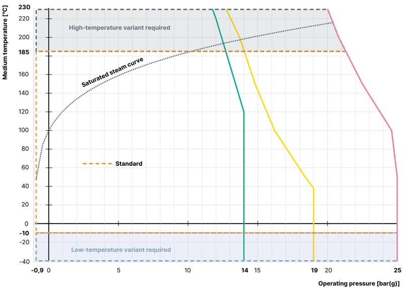
| Medium Temperature [°C] | Permissible Working Pressure [bar(g)] |
|---|---|
| -10 to +50 | 25.0 (capped at 8.5 bar by actuator spring rating) |
| +100 | 24.5 (capped at 8.5 bar by actuator spring rating) |
| +150 | 22.4 (capped at 8.5 bar by actuator spring rating) |
| +185 (Max. Rated Temp) | 21.0 (capped at 8.5 bar by actuator spring rating) |
| +200 | 20.3 |
| +230 | 19.0 |
BURKERT 360873 may be mounted in any orientation, though vertical positioning with the actuator facing upward is recommended.
Actuator Removal for Welding
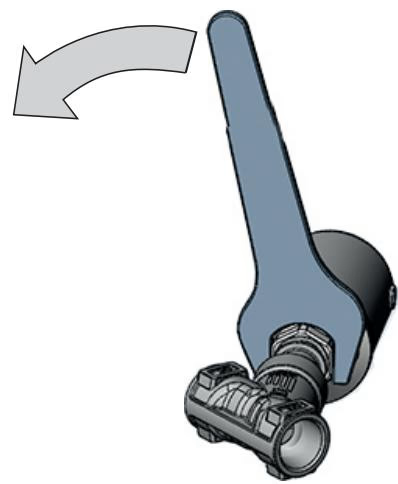
Before welding the CF3M valve body into the pipeline, the pneumatic actuator must be dismantled from the body. Leaving the actuator attached during orbital or manual welding will destroy the internal PTFE seals, PEEK spindle guide, and FKM piston seals through excessive heat conduction.
| Nominal Diameter | Actuator Size | Tightening Torque [Nm] | Tolerance [Nm] |
|---|---|---|---|
| DN 15 | 40 (C), 50 (D), 63 (E) | 45 | +10 / -5 |
| DN 20 | 40 (C), 50 (D), 63 (E), 80 (F) | 50 | +10 / -5 |
| DN 25 | 50 (D), 63 (E), 80 (F) | 60 | +10 / -5 |
| DN 32 (Model 360873) | 63 (E), 70 (M), 80 (F), 100 (G) | 65 | +10 / -5 |
| DN 40 | 63 (E), 70 (M), 80 (F), 100 (G), 125 (H) | 65 | +10 / -5 |
| DN 50 | 63 (E), 70 (M), 80 (F), 90 (N), 100 (G), 125 (H) | 70 | +10 / -5 |
| DN 65 | 80 (F), 100 (G), 125 (H) | 70 | +10 / -5 |
| DN 80 | 125 (H), 130 (P) | 120 | +10 / -5 |
The pilot air connections can be aligned freely across a full 360° rotation to match local plant pneumatic routing.
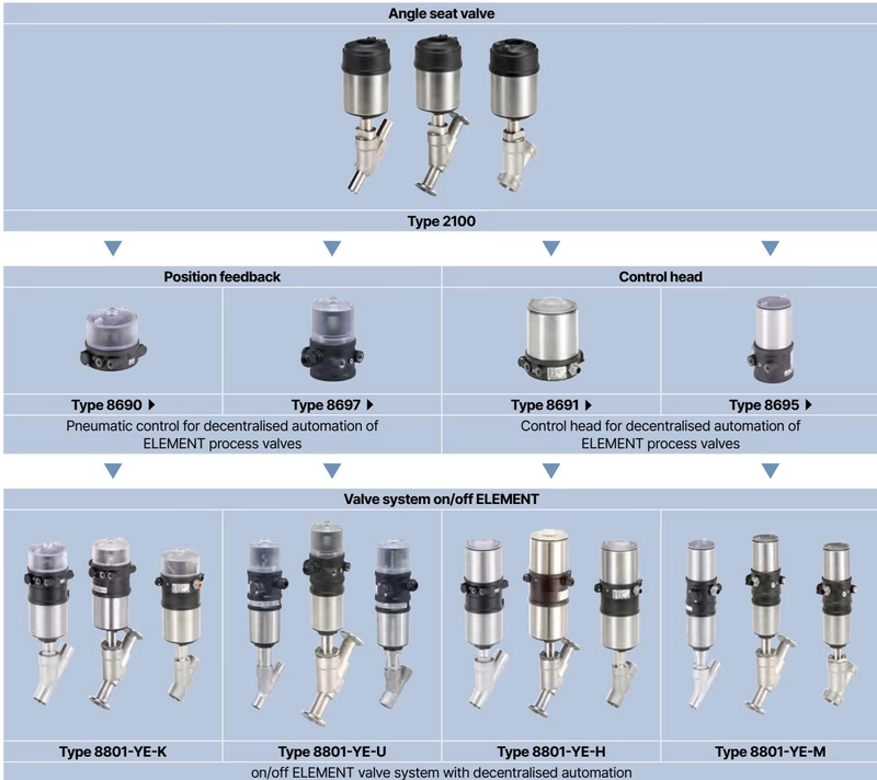
BURKERT 360873 combines directly with BURKERT ELEMENT automation accessories without external brackets or tubing, forming the integrated on/off valve system Type 8801-YE.
Inspect the valve periodically for external leakage around pipe connections, the seat interface, and the relief bore.
| Fault Observed | Potential Cause | Corrective Action |
|---|---|---|
| Actuator does not switch | Pilot air connected to wrong port | Connect control pressure (min. 4.8 bar) directly to pilot air port 1 |
| Pilot pressure below threshold | Increase pilot air pressure to within 4.8–10.0 bar(g) | |
| Operating line pressure exceeds 8.5 bar | Reduce line pressure to permissible specification | |
| Valve does not seal tightly | Debris trapped between seat and disc | Disassemble valve body and clean internal seat surface |
| Worn or scored PTFE seat disc | Replace swivel plate assembly with original Burkert spare kit | |
| Medium leaking from relief bore | Damaged or worn packing gland V-rings | Replace gland packing set using installation tool (Socket 683223) |
Explore similar products in our catalog



