


PN25

BURKERT 377555 (Type 2100) is a pneumatically operated 2/2-way angle seat valve with NC function, stainless steel body, DN25 ASME BPE weld ends, PTFE seat seal, and 0-9 bar operating pressure.
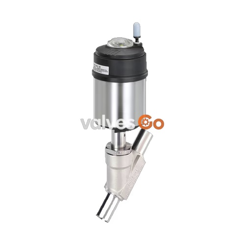
BURKERT 377555 (Type 2100) is a pneumatically operated 2/2-way angle seat valve from the ELEMENT series, configured for decentralized process automation. The valve features a DN25 orifice, ASME BPE weld ends (outer diameter 25.4 mm x wall thickness 1.65 mm), an actuator size of Ø 50 mm (Size D), and control function A (normally closed by spring force). Fluid enters below the valve seat, allowing reliable shut-off for liquids, steam, and gases without water hammer. Designed with a cast CF3M stainless steel body and PTFE seat sealing, the unit provides tight shut-off up to 9 bar(g) operating pressure, with medium temperatures up to +185 °C and full CIP/SIP capability.

BURKERT 377555 utilizes control function A (CFA). In its rest position, the valve is held closed by spring force acting on the piston and spindle assembly. Applying pilot air pressure to pilot port 1 lifts the piston against the spring stack, raising the swivel plate off the valve seat into the open position. When pilot air is vented, the springs return the spindle and swivel plate to the closed position.
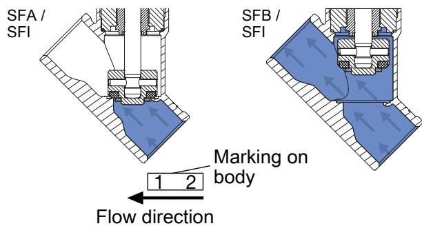
The flow direction is configured below the seat (flow-to-open). Because the operating medium acts on the underside of the swivel plate, process pressure aids in opening the valve. This flow configuration is required for liquid applications to prevent dangerous pressure surges.
Operating Restriction on Liquid Media
Valves with flow direction above the seat must not be used for liquid media. Rapid closure against flowing liquid produces severe water hammer that can burst pipelines and equipment. BURKERT 377555 is configured with flow direction below the seat, making it fully rated for liquids, steam, and gases.
BURKERT 377555 incorporates corrosion-resistant materials throughout its wetted and external structural parts. The stem seal utilizes a self-adjusting PTFE V-ring packing gland with integrated spring compensation, ensuring zero maintenance and long cycle life. Lubricants used in the packing gland and pneumatic actuator are certified according to NSF H1.
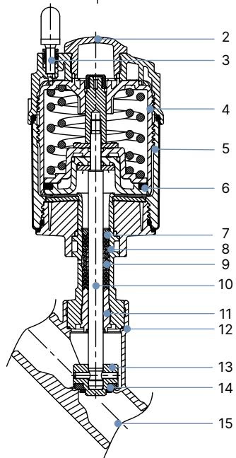
| Item No. | Component | Material |
|---|---|---|
| 1 | Ground terminal | Stainless steel 1.4301 / 1.4305 (ATEX variants) |
| 2 | Optical position indicator | Polysulfone (PSU) |
| 3 | Pilot air port | G 1/8" internal thread (Standard: PP push-in connector) |
| 4 | Actuator cover | Polyphenylene sulphide (PPS) |
| 5 | Actuator casing | Stainless steel 1.4561 (316Ti) |
| 6 | Piston seal | FKM |
| 7 | Spring | Stainless steel 1.4310 |
| 8 | Pipe | Stainless steel 1.4401 (316) / 1.4404 (316L) |
| 9 | Packing gland | Filled PTFE V-rings with spring compensation |
| 10 | Spindle | Stainless steel 1.4401 (316) / 1.4404 (316L) |
| 11 | Spindle guide | PEEK |
| 12 | Body seal | Graphite (Option: PTFE) |
| 13 | Swivel plate | Stainless steel 1.4401 (316) / 1.4404 (316L) |
| 14 | Seat seal | PTFE (Option: PEEK) |
| 15 | Valve body | Cast stainless steel CF3M |
BURKERT 377555 is rated for continuous operating pressures up to 9 bar(g) with a minimum pilot pressure requirement of 5.2 bar(g). The water flow coefficient (Kv) is 13 m³/h, measured at +20 °C with 1 bar differential pressure.
| Technical Parameter | Specification Value |
|---|---|
| Operating medium | Steam, water, alcohols, oils, fuels, hydraulic fluids, saline solutions, lyes, organic solvents, neutral gases |
| Medium temperature range | -10 °C to +185 °C |
| Ambient temperature range | -10 °C to +100 °C (with threaded pilot air bushing) |
| Viscosity limit | Max. 600 mm²/s |
| Control medium | Clean dry air or neutral gases |
| Minimum pilot pressure | 5.2 bar(g) |
| Maximum pilot pressure | 10.0 bar(g) |
| Maximum operating pressure | 9.0 bar(g) |
| Flow coefficient (Kv water) | 13 m³/h |
| Seat leakage | Leakage rate A according to DIN EN 12266-1 |
| Protection rating | IP65 / IP67 according to EN 60529, NEMA Type 4X |
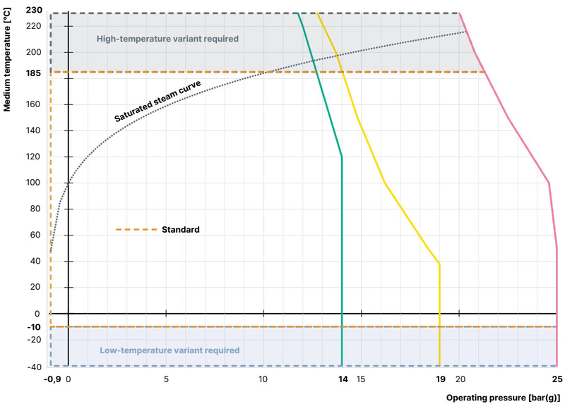
The maximum permissible working pressure reduces at elevated process temperatures according to ASME B16.34 Class 150 and DIN EN 12516-1 PN25 standards:
| Medium Temperature [°C] | Max. Permissible Pressure PN25 [bar] | Max. Permissible Pressure Cl.150 [bar] |
|---|---|---|
| -10 to +38 / +50 | 25.0 | 19.0 |
| 100 | 24.5 | 16.2 |
| 150 | 22.4 | 14.8 |
| 185 | 20.9 | 14.0 |
| 200 | 20.3 | 13.7 |
| 230 | 19.0 | 12.7 |
BURKERT 377555 combines an actuator size of Ø 50 mm (Size D) with a DN25 welded body conforming to ASME BPE / DIN 11866 Series C.
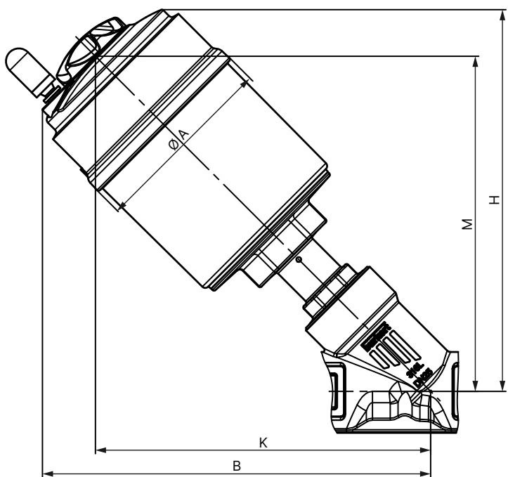
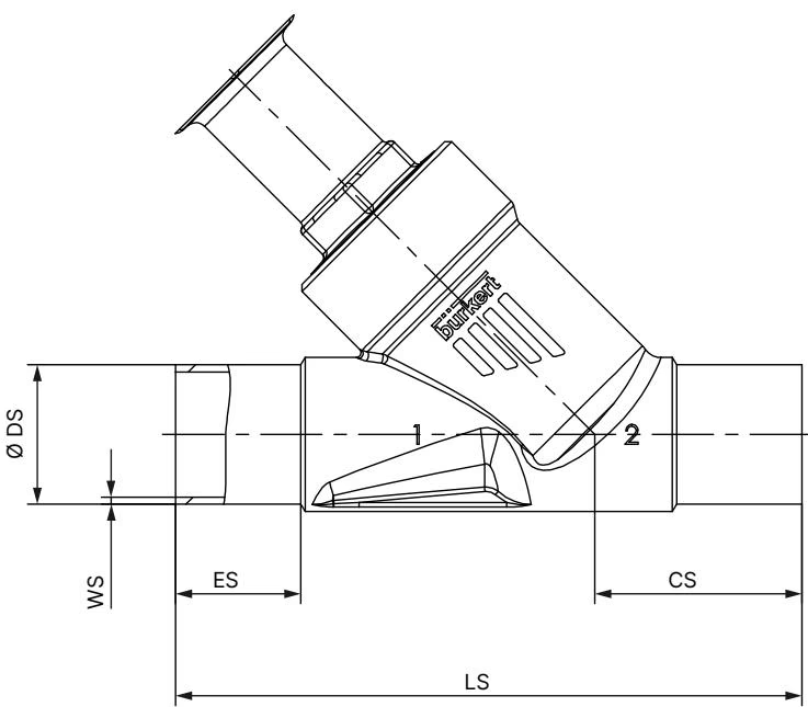
| Dimension Code | Description | Dimension [mm] |
|---|---|---|
| DN / NPS | Nominal size | DN 25 / NPS 1" |
| Actuator Size Ø | Actuator casing external size | 50 mm (Size D) |
| Ø A | Actuator casing outside diameter | 64.5 mm |
| B | Max. total height to top of actuator | 175 mm |
| H | Height to center of pilot air port | 173 mm |
| K / M | Port center to body connection lower edge | 156 mm |
| LS | Face-to-face body installation length | 152 mm |
| ES | Weld end insertion length | 30 mm |
| CS | Port center to pipe end offset | 51 mm |
| Ø DS | Outer pipe diameter | 25.4 mm (1.00") |
| WS | Pipe wall thickness | 1.65 mm (0.065") |
| Inner Ø | Inner pipe diameter | 22.1 mm |
BURKERT 377555 can be installed in any physical position, preferably with the actuator upright.
Disassemble Actuator Before Welding
To protect the internal seals, spindle guides, and PPS actuator housing from thermal damage during pipeline welding, remove the actuator assembly from the valve body before welding. Apply 5.0 bar pneumatic pilot pressure to pilot port 1 to lift the swivel plate into the open position, hold the body hex flat with a wrench, and unscrew the actuator from the body.
When reinstalling the actuator onto the valve body, inspect the body seal, grease threads with Klüber paste UH1 96-402, and pressurize pilot port 1 with 5 bar air to keep the swivel plate lifted off the seat. Tighten according to the nominal diameter:
| Nominal Diameter DN | Actuator Size | Tightening Torque [Nm] | Tolerance [Nm] |
|---|---|---|---|
| DN 15 | 40 (C), 50 (D), 63 (E) | 45 | +10 / -5 |
| DN 20 | 40 (C), 50 (D), 63 (E), 80 (F) | 50 | +10 / -5 |
| DN 25 | 50 (D) | 60 | +10 / -5 |
| DN 32 | 63 (E), 80 (F), 100 (G) | 65 | +10 / -5 |
| DN 40 | 63 (E), 80 (F), 100 (G), 125 (H) | 65 | +10 / -5 |
| DN 50 | 63 (E), 70 (M), 80 (F), 90 (N) | 70 | +10 / -5 |
The pilot air connections can be rotated through 360° to simplify pneumatic tubing routing.
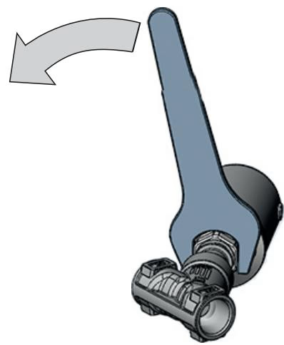
Rotation Direction Restriction
Pressurize pilot air port 1 with 5 bar air to open the valve before turning the actuator. Turn the actuator nut only in the direction shown on the housing mark while counter-holding the body hex. Turning in the opposite direction will loosen the body connection and compromise valve sealing.
BURKERT 377555 features a G 1/8" female pilot air port (Port 1). Connect compressed air supplied with a minimum pilot pressure of 5.2 bar(g) and maximum 10 bar(g). Clean dry instrument air conforming to ISO 8573-1 is recommended. In aggressive operating environments, route exhaust air from open pneumatic vents to a neutral atmosphere using tubing.
Food Contact Conformity
Wetted materials comply with EC Regulation 1935/2004 based on the manufacturer's declaration. The unit is fully compatible with CIP (Clean-in-Place) and SIP (Steam-in-Place) cleaning cycles up to +185 °C.
Perform regular visual inspections during planned maintenance intervals:
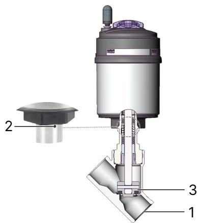
| Inspection Area | Check Item | Corrective Action |
|---|---|---|
| 1 | Process pipe weld connections | Inspect welds and re-weld/repair if leakage is observed |
| 2 | Relief bore on actuator neck | Check for medium discharge; replace packing gland or actuator assembly |
| 3 | Swivel plate and valve seat | Check for internal pass-through leakage; replace swivel plate / seat seal set |
| Fault Symptom | Probable Cause | Corrective Action |
|---|---|---|
| Actuator fails to switch | Pilot air connected to incorrect port | Connect pilot supply to pilot port 1 |
| Pilot pressure below 5.2 bar | Increase pilot air pressure to specified minimum | |
| Operating medium pressure exceeds 9 bar | Reduce process line pressure to rated limit | |
| Pipeline flow direction reversed | Verify body flow arrow points in the flow direction | |
| Seat passes fluid when closed | Pilot pressure insufficient or line pressure exceeds limit | Restore correct operating and pilot pressure limits |
| Debris lodged between seal and valve seat | Flush system or dismantle valve body to remove debris | |
| Swivel plate PTFE seal worn or damaged | Install replacement swivel plate kit | |
| Medium escapes from relief bore | Packing gland V-rings worn | Replace packing gland using socket tool (Part no. 683221, A/F 19 mm) |
BURKERT 377555 can be integrated directly with ELEMENT modular automation accessories to form automated valve systems (Type 8801-YE):
Explore similar products in our catalog



