PN100

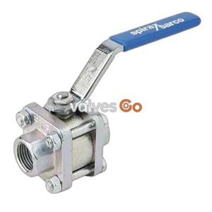
Spirax Sarco KBV21 carbon steel manual boiler blowdown ball valve. Features reinforced PTFE seats, DN25-DN65 sizes, and a safety interlock handle that can only be removed when closed.
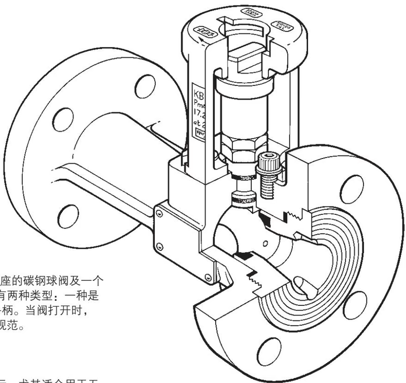
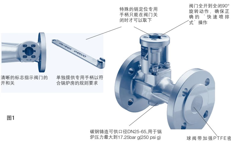
The Spirax Sarco KBV21 is a manual boiler blowdown valve comprising a carbon steel ball valve with a reinforced PTFE seat and a stainless steel manual handle. Designed specifically for boiler blowdown applications, it is particularly suitable for systems that do not require timed automatic blowdown. A key safety feature of the KBV21 is its interlock mechanism: the manual handle cannot be removed when the valve is open, ensuring strict compliance with boiler house regulations.
Two types of handles are available (supplied separately): a standard length handle and an extended 'T' handle for blowdown valves located in restricted spaces.
Note: DN32 is available in PN40 only.
| Parameter | Value |
|---|---|
| Maximum Allowable Pressure | 17.25 bar g at 208°C (250 psi g at 406°F) |
| Cold Hydraulic Test Pressure | 60 bar g (PN40) 78 bar g (Class 300) |
| Seat Leakage Test | 6 bar g (Air under water) |
| Part | Material | Standard |
|---|---|---|
| Body | Carbon Steel | ASTM A216 WCB |
| Seat and Stem Seal | Reinforced PTFE | - |
| Ball | Austenitic Stainless Steel | AISI 316 |
| Stem | Stainless Steel | AISI 420 or 316 |
| Sleeve | Austenitic Stainless Steel | AISI 316L |
| Connector | Austenitic Stainless Steel | AISI 316L |
| Standard Handle* | Austenitic Stainless Steel | AISI 316L |
| 'T' Handle* | Carbon Steel | - |
Note: Standard handle and 'T' handle are supplied separately.
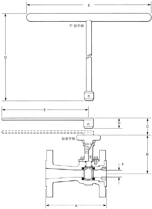
Approximate dimensions in mm and weights in kg.
| Size | A | B | C | D | E | F | Weight |
|---|---|---|---|---|---|---|---|
| DN25 | 165 | 114 | 35 | - | - | 21 | 6.0 |
| DN32 | 178 | 117 | 35 | - | - | 23 | 7.5 |
| DN40 | 190 | 126 | 35 | - | - | 31 | 9.8 |
| DN50 | 216 | 134 | 35 | - | - | 38 | 12.0 |
| DN65 | 241 | 146 | 35 | - | - | 51 | 18.0 |
| Standard Handle* | - | - | - | 32 | 258 | - | - |
| 'T' Handle* | - | - | - | 500 | 375 | - | - |
WARNING
Ensure the boiler is drained and vented to atmosphere before installation or maintenance.
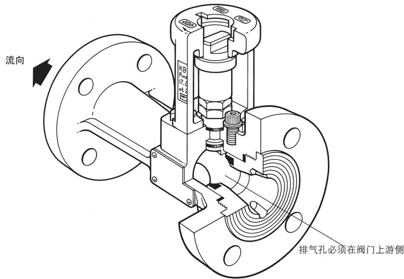
Check that the blowdown valve and inlet pipe sizes match. Determine the correct pipe length and align the pipe with the valve center to avoid stress. The valve must be installed in the direction of fluid flow as indicated by the arrow.
It is recommended to check the valve for debris and corrosion during boiler overhauls. Check the stem for leaks. If there is a minor leak, tighten the gland nut to a torque of 24-30 Nm (18-22 lbf ft).
DANGER
The ball valve may trap pressurized media within the valve cavity. Ensure there is no pressure at the valve inlet, outlet, or inside the valve before loosening and removing the flange bolts.
If the valve requires re-polishing (or just removal for inspection), a special tool is required to remove the screwed-in insert. This tool can be made from a steel plate of suitable thickness (with rounded corners) to fit into the corresponding holes of the seal packing.
For blowdown applications, carbon-reinforced PTFE stem seals should be used instead of graphite seals.
Use the special tool to remove the insert contained in the valve. Significant force may be required to open the joint; use a vice if necessary. Penetrating oil can be used to help remove the seal packing, but do not use heat.
DANGER
If aged fluoroelastomer 'O' rings are exposed to temperatures of 315°C (599°F) or higher, they may decompose and produce hydrofluoric acid. Avoid skin contact and inhalation of any fumes, as this acid can cause severe burns and damage the respiratory system.
Once the insert is removed, the ball can be taken out. To remove the stem, first loosen the lock nut and gland nut, then gently tap the stem into the body using a soft-faced hammer to avoid damaging the stem threads.
A complete set of spare parts is available, including all seal packings, gasket kits, and the valve ball. Stem spares are also available.
INFO
The vent hole on the ball must be on the upstream side of the valve.
When ordering, please specify the valve type, application (e.g., boiler blowdown), and size (DN).
Explore similar products in our catalog