98% Separation Efficiency

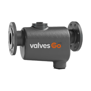
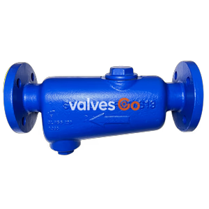
TLV DC3A cyclone separator with built-in free float air trap. Features 98% condensate separation efficiency, 10 barg PMO, and ductile cast iron body for air lines.
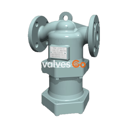
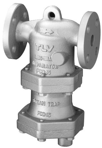
TLV DC3A cyclone separator and air trap incorporated into one unit provide high-quality dry air. For use on mains and branches, it utilizes centrifugal force to separate condensate from air and features a built-in free float air trap for the automatic discharge of the collected condensate. The separator achieves condensate separation efficiency as high as 98%.
WARNING
Do not use for toxic, flammable or otherwise hazardous fluids. To avoid abnormal operation, accidents or serious injury, DO NOT use this product outside of the specification range. Local regulations may restrict the use of this product to below the conditions quoted.
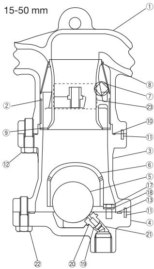
| No. | Description | Material | DIN/EN | ASTM/AISI |
|---|---|---|---|---|
| 1 | Body (Screwed / Flanged) | Ductile Cast Iron | 0.7040 / 0.7043 | A536 / A395 |
| 2 | Separator Body | Cast Iron / Ductile Cast Iron | 0.6025 / 0.7043 | A126 Cl.B / A395 |
| 3 | Trap Cover | Cast Iron / Ductile Cast Iron | 0.6025 / 0.7043 | A126 Cl.B / A395 |
| 4 | Separator | Cast Stainless Steel | 1.4312 | A351 Gr.CF8 |
| 5 | Float | Stainless Steel SUS316L | 1.4404 | AISI316L |
| 6 | Float Cover | Cast Iron / Ductile Cast Iron | 0.6025 / 0.7043 | A126 Cl.B / A395 |
| 7 | Guide Pin | Stainless Steel SUS304 | 1.4301 | AISI304 |
| 8 | Trap Valve Seat | Nitrile Rubber / Stainless Steel | - / 1.4305 | D2000BF / AISI303 |
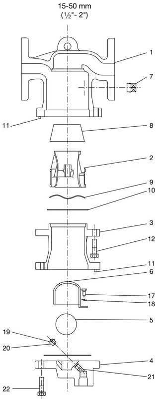
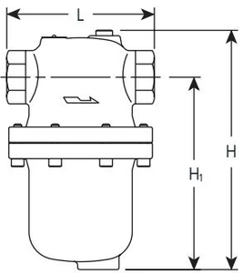
Screwed: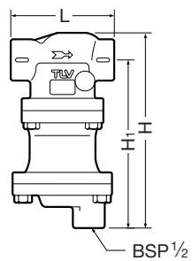
Flanged: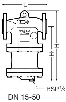
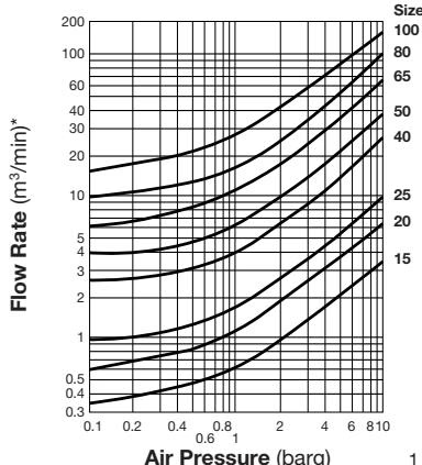
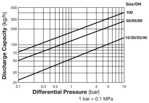
A visual inspection can be carried out to aid in determining the necessity for immediate maintenance or repair, if the trap is open to atmosphere. Operational inspections should be performed at least twice per year, or as called for by trap operation conditions.
| Condition | Characteristic |
|---|---|
| Normal | Condensate is discharged continuously with flash steam and the sound of flow can be heard. If there is very little condensate, there is almost no sound of flow. |
| Blocked | No condensate is discharged. The trap is quiet and makes no noise, and the surface temperature of the trap is low. |
| Blowing | Live steam or air continually flows from the outlet and there is a continuous metallic sound. |
| Leakage | Live steam or air is discharged through the trap outlet together with the condensate and there is a high-pitched sound. |
DANGER
NEVER apply direct heat to the float. The float may explode due to increased internal pressure, causing accidents leading to serious injury or property and equipment damage.
| Parts Inspection Procedure | Check Criteria |
|---|---|
| Body, Cover(s) | Check inside for damage, dirt, grease, oil film, rust or scale |
| Gaskets | Check for warping or damage |
| Screen | Check for clogging, corrosion or damage |
| Float | Check for deformation, damage, oil film or water inside |
| Valve Seat | Check for rust, scale, oil film, wear or damage |
| Problem | Cause | Remedy |
|---|---|---|
| No condensate is discharged or discharge is poor (blocked) | Float is damaged or filled with condensate | Replace the float |
| Trap valve seat port, screen or piping is clogged with rust or scale | Clean | |
| The trap operating pressure exceeds the maximum specified pressure, or there is insufficient pressure differential | Compare specifications and actual operating conditions | |
| Air is discharged or leaks from the trap outlet (blowing / leakage) | Rust and scale have accumulated around the trap valve seat or under the float | Clean |
| The trap valve seat is damaged | Replace with a new trap valve seat | |
| Float is deformed or coated with scale | Clean or replace the float | |
| Separator is installed above the maximum allowable inclination angle | Correct the installation | |
| Air is leaking from sealing surfaces | Deterioration of or damage to gaskets | Replace with new gaskets |
| Improper tightening torques were used | Tighten to the proper torque | |
| Water is mixed with the air at the separator outlet | Air flow velocity is too high | Take steps necessary to lower the flow velocity |
Explore similar products in our catalog