98% Separation Efficiency

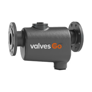
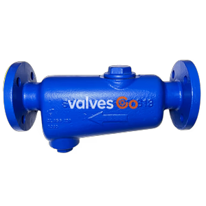
Yoshitake DS-2 cyclone type drain separator for steam and air piping. Features ductile cast iron body, low pressure loss, 2.0 MPa max pressure, and flanged connections up to 150A.
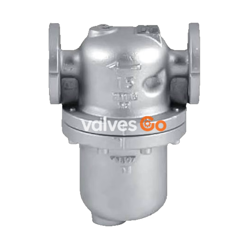
Yoshitake DS-2 drain separator is designed to efficiently separate condensate from steam and compressed air systems. Utilizing a cyclone-type internal structure, it generates centrifugal force to remove moisture, which helps prevent thermal efficiency decline, water hammer, and corrosion in valves and piping. The DS-2 features flanged connections and is available in sizes from 15A to 150A, handling maximum pressures up to 2.0 MPa for steam and 1.0 MPa for air.
Also sharing the product family is the DS-1 drain separator, which offers similar performance with JIS Rc screwed connections for sizes 15A to 50A. Both models are virtually maintenance-free due to the absence of moving parts, relying on their flow path geometry to ensure reliable, permanent condensate separation with extremely low pressure loss.
Failure to properly handle condensate in steam piping and air/gas systems can result in various issues:
When steam or air flows into the drain separator, centrifugal force is generated by the internal structure. Condensate circles along the internal surface of the body due to the difference in specific gravity and strikes against the baffle. It is then guided to the discharge port, while clean, dry steam or air flows to the outlet through the nozzle.

INFO
There are no movable parts. The capacity will not change almost permanently, as the design itself makes this performance possible.
| Model | DS-1 | DS-2 | DS-2 (150A) |
|---|---|---|---|
| Nominal Size | 15A-50A | 15A-100A | 150A |
| Application | Steam, Air | Steam, Air | Steam, Air |
| Maximum Pressure | 2.0 MPa (Air: 1.0 MPa or less) | 2.0 MPa (Air: 1.0 MPa or less) | 1.8 MPa (Air: 1.0 MPa or less) |
| Maximum Temperature | 220°C | 220°C | 220°C |
| Body Material | Ductile cast iron | Ductile cast iron | Ductile cast iron |
| Connection | JIS Rc screwed | JIS 10K/20K FF flanged | JIS 10KFF / 20KRF flanged |
Note: For JIS 10KFF and JIS 10KRF flanges, maximum pressure is 1.0 MPa. A gasket is durable for 1 to 2 years when applied to steam.
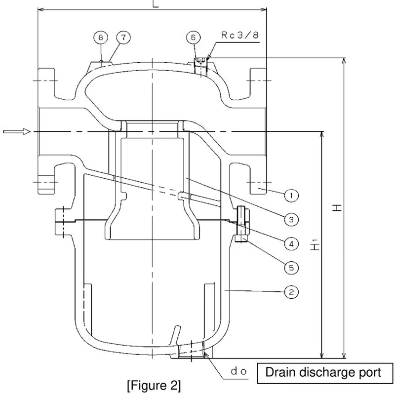
| No. | Parts Name | No. | Parts Name |
|---|---|---|---|
| 1 | Body | 5 | Bolt |
| 2 | Receiver | 6 | Plug |
| 3 | Nozzle | 7 | Name Plate |
| 4 | Gasket | 8 | Rivet |
(DS-2 sizes 15A-100A structure shown. DS-1 uses a similar internal structure with screwed ends. DS-2 150A includes additional parts like a baffle plate and eye bolt.)
Select a drain separator nominal size equivalent to that of the piping. Using a smaller nominal size increases pressure loss and may cause inadequate pressure at the equipment inlet.
Working Flow Velocity:
WARNING
Keep the fluid below the specified flow velocity. A higher flow velocity may cause condensate separation to fail.
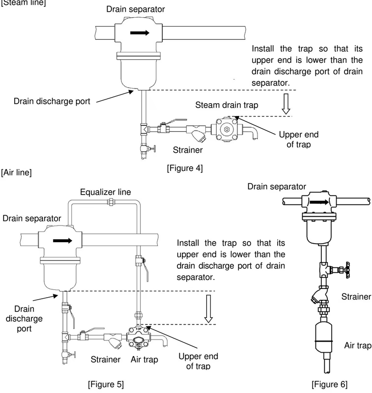
Installation Guidelines:
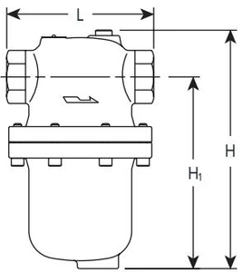
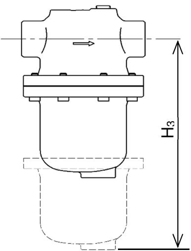
Maintenance Space: Reserve adequate space (dimension H3) below the separator for maintenance and inspections.
Perform a self-inspection once a year to check for abnormalities on the body and receiver, slackness of bolts, and external leakage.
WARNING
Before disassembling or inspecting the product, confirm that internal pressures have been released to the atmosphere and the product has cooled down. Failure to do so may result in injury or burns.
Tightening Torques for Assembly:
When replacing the gasket, clean the faces of the body and receiver, and apply recommended paste on the gasket before reassembly. Tighten bolts evenly in a diagonal order.
Yoshitake Steam & Air Separators
DS series steam separators for removing entrained water from steam lines and improving downstream steam quality.
Explore similar products in our catalog