PN25
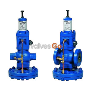
Yoshitake GPK-2001 and GPK-2003 remote control steam pressure reducing valves. Features external sensing, 0.05-1.4 MPa reduced pressure, and ductile cast iron body for precise pneumatic circuit operation.
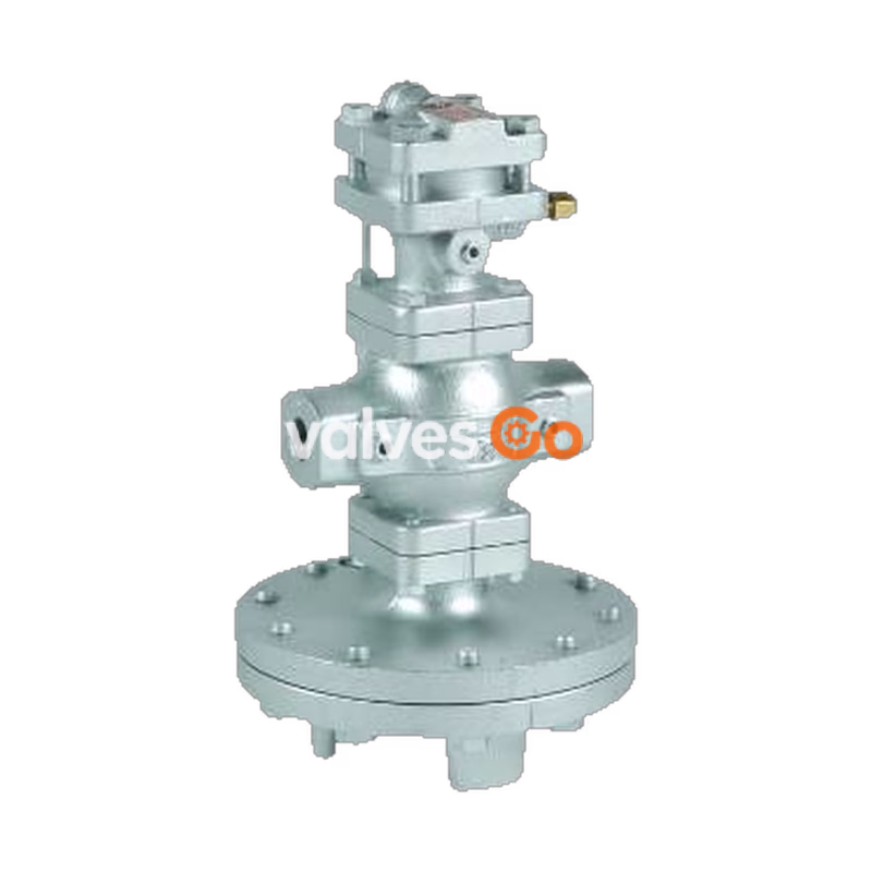
Yoshitake GPK-2001 and GPK-2003 are remote control steam pressure reducing valves. They are superior to piston type valves in capacity and performance, being very effective in controlling inlet pressure and flow rate fluctuations. The spherical main valve offers great sealability and significantly reduces valve seat leakage (compliant with ANSI Class IV). The remote control capability makes pressure adjustment easy with a wide pressure setting range. The GPK-2001 and GPK-2003 can be selected based on the loading air pressure.
| Specification | GPK-2001 | GPK-2003 |
|---|---|---|
| Application | Steam | Steam |
| Sensing Method | External sensing | External sensing |
| Connection | JIS Rc screwed, JIS 20K RF flanged, JIS 10K FF flanged | JIS Rc screwed, JIS 20K RF flanged, JIS 10K FF flanged |
| Nominal Size | 15–50A (Screwed), 15–100A (Flanged) | 15–50A (Screwed), 15–100A (Flanged) |
| Inlet Pressure | 0.1–2.0 MPa (JIS Rc, 20K), 0.1–1.0 MPa (JIS 10K) | 0.25–2.0 MPa (JIS Rc, 20K), 0.25–1.0 MPa (JIS 10K) |
| Reduced Pressure | 0.05–0.9 MPa (JIS Rc, 20K), 0.05–0.85 MPa (JIS 10K) | 0.2–1.4 MPa (JIS Rc, 20K), 0.2–0.85 MPa (JIS 10K) |
| Min. Differential | 0.05 MPa | 0.05 MPa |
| Max. Reducing Ratio | 20:1 | 10:1 |
| Max. Temperature | 220°C | 220°C |
| Part | Material |
|---|---|
| Body | Ductile cast iron |
| Main Valve | Stainless steel |
| Main Valve Seat | Stainless steel |
| Pilot Valve | Stainless steel |
| Diaphragm | Stainless steel |
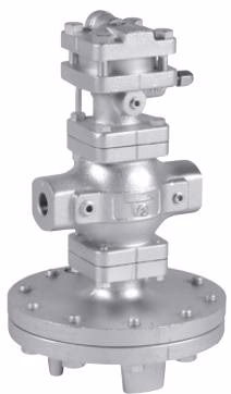
Screwed Type (JIS Rc)
| Nominal Size | L (GPK-2001) | L (GPK-2003) | H (GPK-2001) | H (GPK-2003) | Weight (GPK-2001) | Weight (GPK-2003) |
|---|---|---|---|---|---|---|
| 15A | 150 | 150 | 335 | 353 | 14.0 kg | 17.5 kg |
| 20A | 150 | 150 | 335 | 353 | 14.0 kg | 17.5 kg |
| 25A | 160 | 160 | 341 | 359 | 18.5 kg | 22.0 kg |
| 32A | 180 | 180 | 371 | 389 | 21.5 kg | 25.0 kg |
| 40A | 180 | 180 | 371 | 389 | 21.5 kg | 25.0 kg |
| 50A | 230 | 230 | 435 | 453 | 33.0 kg | 36.5 kg |
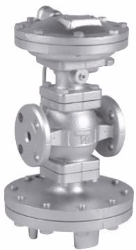
Flanged Type (JIS 20K RF)
| Nominal Size | L | H (GPK-2001) | H (GPK-2003) | Weight (GPK-2001) | Weight (GPK-2003) |
|---|---|---|---|---|---|
| 15A | 146 | 335 | 353 | 15.5 kg | 19.0 kg |
| 20A | 146 | 335 | 353 | 16.0 kg | 19.5 kg |
| 25A | 156 | 341 | 359 | 21.0 kg | 24.5 kg |
| 32A | 176 | 371 | 389 | 24.0 kg | 27.5 kg |
| 40A | 196 | 371 | 389 | 24.5 kg | 28.0 kg |
| 50A | 222 | 435 | 453 | 36.0 kg | 39.5 kg |
| 65A | 282 | 489 | 507 | 64.5 kg | 68.0 kg |
| 80A | 302 | 512 | 530 | 71.5 kg | 75.0 kg |
| 100A | 342 | 595 | 613 | 111.0 kg | 114.5 kg |
| (Note: Length and weight vary slightly for JIS 10K FF connections) |
The pressure reducing valve reduces pressure by throttling the valve. The assembly is composed of the main valve, main valve seat, a pressure adjusting air chamber, the main diaphragm, pilot diaphragm, and a pilot valve for pressure sensing and activation.
Caution
When installing the pressure reducing valve, be sure to connect the provided sensing pipe and joint. Unless the sensing pipe is connected, the valve will not operate. Furthermore, steam may blow off, resulting in burns.
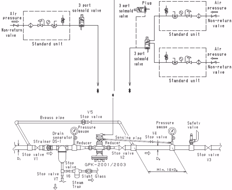
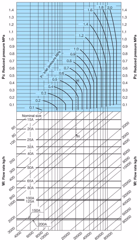
When selecting a nominal size, use the Nominal Size Selection Chart to find the intersection of inlet pressure and reduced pressure. Set the flow rate at 80 to 90% of the rated flow rate, allowing for the pressure and heat loss of the stop valve and strainer to be used before or after the pressure reducing valve.
Installation Recommendations
Explore similar products in our catalog