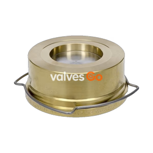
Wafer Type

Yoshitake SCV-16 lift check valve for steam, air, and water pipelines. Features ductile cast iron body, stainless steel valve internals, 1.6 MPa maximum pressure, and 200°C maximum working temperature.
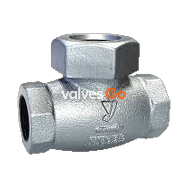
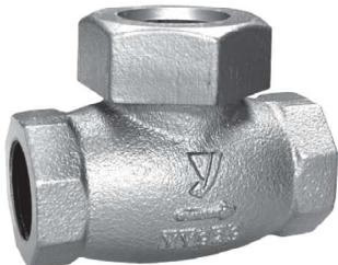
Yoshitake SCV-16 lift check valve prevents backflow of fluid. It is widely used in steam and water pipelines. The valve and the valve seat are made of stainless steel for excellent durability.
Note on Leakage
Do not use the valve in applications that do not allow any valve seat leakage. Since a small amount of fluid leaks out of the product, it cannot be used for applications requiring complete closing.
| Specification | Value |
|---|---|
| Model | SCV-16 |
| Nominal size | 15-50A |
| Application | Steam, Air, Cold and hot water, Oil, non-hazardous fluid |
| Maximum pressure | 1.6 MPa |
| Maximum temperature | 200°C |
| Connection | JIS Rc or NPT screwed |
| Minimum opening pressure | 0.05 MPa |
| Installation posture | Horizontal and vertical |
Pressure and Temperature Ratings:
| Max. working temperature (°C) | -10 to 120 | 150 | 180 | 200 |
|---|---|---|---|---|
| Max. working pressure | 1.6 MPa | 1.4 MPa | 1.3 MPa | 1.2 MPa |
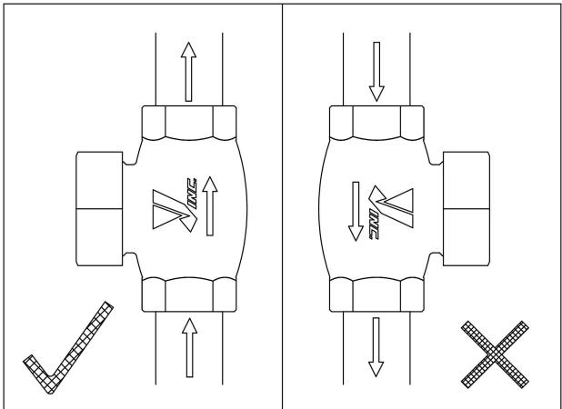
Vertical Installation
When installing the product on a vertical posture, please make the fluid flow from the ground up. The valve can be installed on a vertical pipe only for the flow from bottom to top.
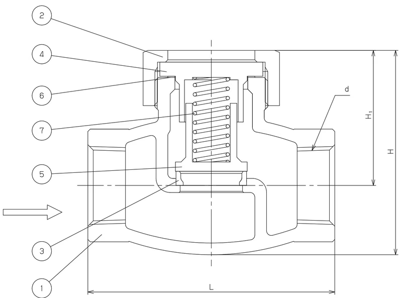
| No. | Name of Parts | Material |
|---|---|---|
| 1 | Body | Ductile Cast Iron (FCD450) |
| 2 | Bonnet Ring | Ductile Cast Iron (FCD450) |
| 3 | Valve Seat | Stainless Steel (SUS403) |
| 4 | Cover | Stainless Steel (SUS304) |
| 5 | Valve | Stainless Steel (SUS304) |
| 6 | Gasket | Copper (C1100) |
| 7 | Spring | Stainless Steel (SUS304) |
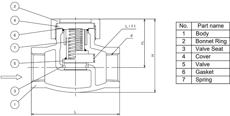
| Nominal size | d | H | L | H1 | Lift | Weight (kg) |
|---|---|---|---|---|---|---|
| 15A | Rc 1/2 / NPT 1/2 | 69.5 | 75 | 48 | 7 | 0.5 |
| 20A | Rc 3/4 / NPT 3/4 | 77.5 | 90 | 52.5 | 11.5 | 0.9 |
| 25A | Rc 1 / NPT 1 | 87 | 105 | 57.5 | 13 | 1.4 |
| 32A | Rc 1-1/4 / NPT 1-1/4 | 101.5 | 120 | 65.5 | 15.5 | 1.9 |
| 40A | Rc 1-1/2 / NPT 1-1/2 | 114 | 135 | 74 | 17.5 | 2.8 |
| 50A | Rc 2 / NPT 2 | 137.5 | 160 | 87.5 | 22.5 | 3.5 |
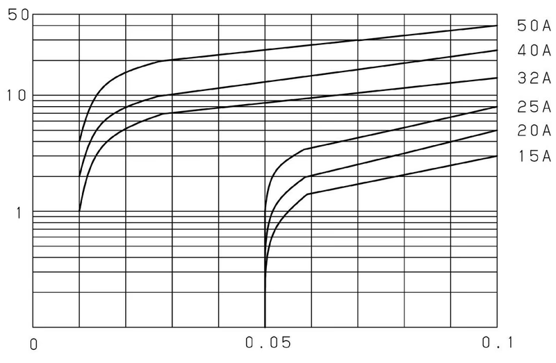
The values listed on the chart below are reference values. It varies depending on the piping conditions and usage environment. Use a safety factor of more than 20% for product selection.
Installation Precautions
Operating Precautions
| Trouble | Cause | Remedy |
|---|---|---|
| Fluid does not flow | 1. Contact surface of valve and valve seat is stuck. 2. Installation direction is wrong. | 1. Replace the product if valve does not move. 2. Confirm the arrow on the product and install it correctly. |
| Fluid flows back | 1. Contact surface of valve and valve seat is worn away. 2. Internal parts are damaged. | Replace the product. |
Maintenance Warning
Completely discharge the pressure inside of the product, line, and equipment before disassembling or maintenance. In the case of high-temperature fluid, cool down the product until it can be touched with bare hands. Failure to follow this notice may result in injury or burns.
Yoshitake Check Valves / Lift Check
CV and SCV lift check valve series for preventing reverse flow in steam, water, and air lines.