Stainless Steel

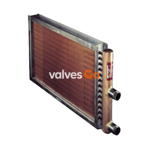
Armstrong 6000 Series heavy duty steam and liquid coils feature mono-metallic construction, welded tube-to-header joints, and ASME Section VIII Div. 1 compliance for high-pressure heating and cooling.
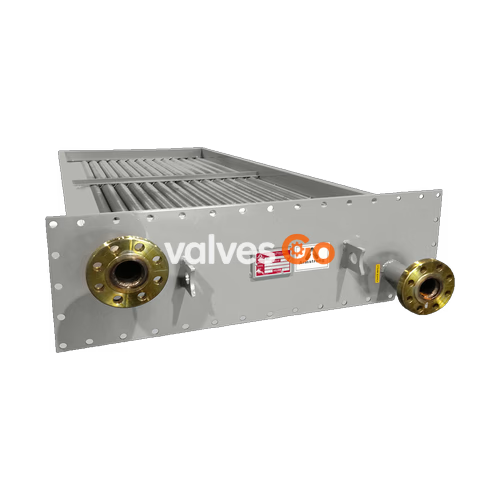
Armstrong 6000 Series heavy duty steam and liquid coils are designed to accommodate the service requirements of demanding industrial installations. They provide a complete range of solutions for heating, cooling, and process drying applications. Built with enough material at the tube-to-header joints to ensure strength, these coils survive the rigors of high pressures, high temperatures, and corrosive conditions. All Armstrong coils are of mono-metallic design, meaning all wetted parts are made of the same materials, which precludes the likelihood of galvanic corrosion often experienced in coils made of dissimilar materials.
The base material found in the 6000 Series coils is steel, with a minimum wall thickness of .109" for steam and liquid coils, affording both strength and internal corrosion resistance. The coils are always of welded construction, providing the most reliable method of connecting the tubes to the headers. Each coil is tested during construction, and the completed unit is hydrostatically tested to not less than 1.3 times the design pressure.
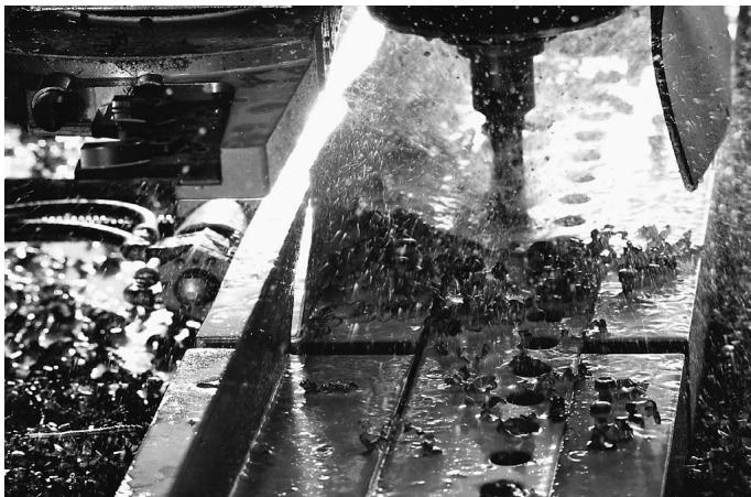
The effective heat transfer of a coil is based on fin pitch, fin height, fin material, and method of attachment. Armstrong offers multiple fin designs to combat dirt buildup and maximize heat transfer.
The keyfin is the standard design for Armstrong’s most popular coils. Keyfin coils are manufactured by forming a helical groove in the tube surface, winding the fin into the groove and peening the displaced metal from the groove against the fin. This ensures a tight fit between the fin and the tube, providing efficient operation over wide temperature ranges. Keyfin is the superior design for dissimilar fin and tube materials.
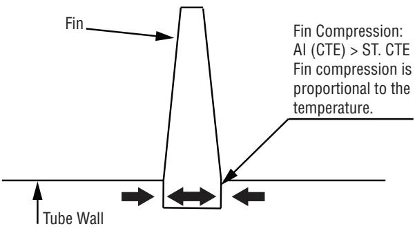
The L fin has a "foot" at its base and is tension wound on knurled tube material. The L-shaped base provides a large contact area between the tube and the fin, ensuring effective, long-lasting heat transfer. The L fin is recommended when tubes and fins are of the same material.
The overlap L fin is simply an L fin with an extended base. Each fin overlaps the foot of the previous fin, completely covering the tube surface. The overlap technique makes it possible to create a completely aluminumized coil for applications where exposed steel would be vulnerable to corrosion.

| Component | Type | Specifications |
|---|---|---|
| Carbon Steel Tubes | Standard | 12 ga A-214 ERW |
| Optional | 10 ga A-214 ERW; 12 ga A-179 seamless; 10 ga A-179 seamless | |
| Carbon Steel Pipes | Optional | Sch 80 seamless; A-106 Gr 'B' |
| Stainless Steel Tubes | Standard | 14 ga (1" OD) 12 ga (1-1/2" OD) A-249 type 304L |
| Optional | 14 ga (1" OD) 12 ga (1-1/2" OD) A-249 type 316L | |
| Steel Fins | Standard | 0.024" thick on 3/4" NPS pipes & 1" OD tubes; 0.036" thick on 1-1/2" OD tubes & 1" NPS & larger pipe |
| Aluminum Fins | Standard | 0.020" thick on all tube sizes; 0.016" thick on 1" OD |
| Optional | 0.030" heavy keyfin 1" & 1-1/2" OD steel and stainless steel tube | |
| Stainless Steel Fins | Standard | 0.020" thick type 304 & 316 on all sizes |
| Copper Fins | Standard | 0.016" thick on all sizes |
| Connections | Steel | Sch 80 (screwed), Sch 40 (flanged) |
| Stainless Steel | Sch 40 (screwed), Sch 10 (flanged) | |
| Headers | All | Welded construction, same material as tubing |
| Casing | Galvanized Steel | Min 12 ga for depth 7-1/2" and over; Min 14 ga for depth under 7-1/2" |
| Stainless Steel | 14 ga type 304 & 316 for all depths (Optional) | |
| Aluminum | 12 ga for all depths (Optional) |
Design and Testing
Standard design pressure for steel coils is 300 psig @ 650°F, stainless steel coils 300 psig @ 500°F. Hot oil coil: 250 psig @ 750°F. All coils are tested hydrostatically to at least 1.3 times the working pressure with a standard testing pressure at 450 psig on steel & stainless steel steam coils. Coils are available with ASME Section VIII, Division I, "U" stamps or CRN approval.
Example: H – S 2 A 09 – Q 08 – 30 x 72 x 6
Successful operation and a long, trouble-free service life depend on proper installation, trapping, and venting.
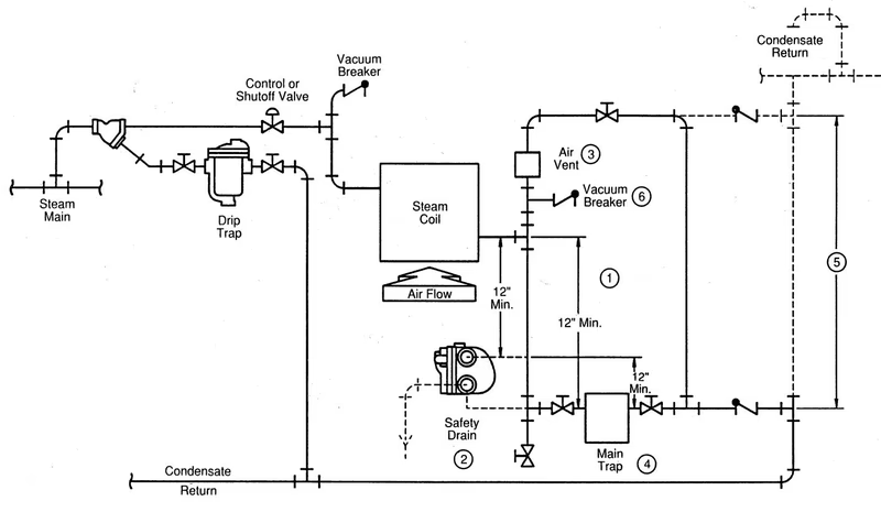
Notes on Piping Practices:
Explore similar products in our catalog