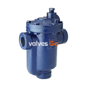
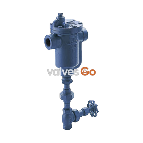
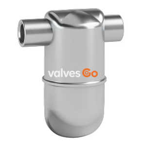
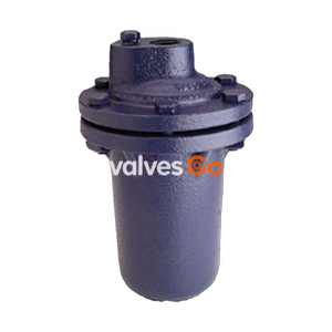
Armstrong 80-DC Series automatic differential condensate controllers (DC) are designed to function on applications where condensate must be lifted from a drain point or in gravity drainage applications where increased velocity will aid in condensate drainage.
When lifting from the drain point, often referred to as syphon drainage, the reduction in pressure that occurs when the condensate is elevated causes a portion of it to flash back into steam. Ordinary steam traps, unable to differentiate between flash steam and live steam, close and impede drainage. Increased velocity with gravity drainage will aid in drawing the condensate and air to the DC. This increased velocity is caused by an internal steam by-pass, controlled by a manual metering valve, so the condensate controller will automatically vent the by-pass or secondary steam. This is then directed to the condensate return line or collected for use in other heat exchangers.
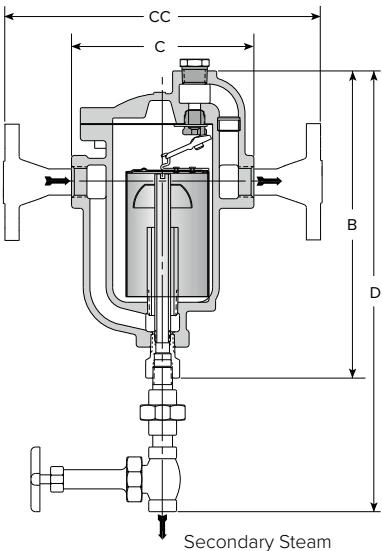
Dimensions and Weights
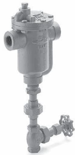
| Model No. | 81-DC | 82-DC | 83-DC | 84-DC | 85-DC | 86-DC |
|---|
| Inlet & Outlet Connections (in) | 3/4 | 3/4 | 1 | 1-1/4 | 2 | 2 |
| Inlet & Outlet Connections (mm) | 20 | 20 | 25 | 32 | 50 | 50 |
| Secondary Steam Connection | 3/8" | 1/2" | 1/2" | 3/4" | 1" | 1-1/2" |
| "A" Diameter (mm) | 95 | 143 | 178 | 203 | 229 | 292 |
| "B" Height (mm) | 203 | 267 | 330 | 381 | 445 | 584 |
| "C" Face-to-Face screwed (mm) | 127 | 165 | 197 | 229 | 260 | 330 |
| "CC" Face-to-Face flanged PN40 (mm) | 191 | 229 | 261 | 355 | 398 | 468 |
| "L" Height valve included (mm) | 337 | 445 | 476 | 552 | 610 | 813 |
| Weight screwed (kg) | 3.4 | 7.9 | 13.7 | 21.3 | 34.0 | 63.0 |
| Weight flanged PN40 (kg) | 5.3 | 9.4 | 15.3 | 25.5 | 39.0 | 69.0 |
INFO
Other flange sizes, ratings and face-to-face dimensions are available on request. All dimensions and weights are approximate.
Installation Recommendations
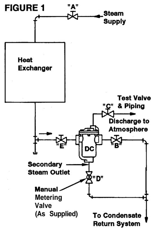
Installation Guidelines
- Locate Controller below equipment being drained when possible.
- Full pipe size connections should be used to Controller inlet, outlet and secondary steam discharge.
- Provide hand valves "E" and "B" as shown in the diagram. These not only provide proper isolation for repair but are necessary when adjusting operation of Controller during initial start-up.
- Provide a "test valve" hook-up ("C" in diagram).
- The manual metering valve ("D" in diagram), as supplied with the DC Controller, can be relocated to a horizontal position if necessary to reduce overall vertical installation height.
Start-Up & Operating Procedure
- The following valve settings should be made on initial start-up of equipment:
- Valves "A", "B" and "E" open
- Valves "C" and "D" closed With these valve settings, the Differential Controller is functioning as a standard inverted bucket steam trap. Continue to operate in this condition until system has reached operating conditions of pressure and temperature.
- Close valve "B" on the condensate discharge of controller and open test valve "C". Condensate being discharged through the Controller is now observed at test valve piping to atmosphere. Note the cycle rate of condensate discharge. (This would be typical of the operation of a standard inverted bucket trap.) Important: If the condensate discharge is continuous, never cycling, the Differential Controller selected may be too small for the required load.
- Open manual metering valve "D" 1/4 turn from the full closed position. Observe the condensate discharge cycle rate. A definite increase in the cycle rate should occur over that observed in Step 2 above. If no increase in cycle rate is observed with this setting, open the manual metering valve an additional 1/4 turn and again observe the discharge cycle rate. (Allow three or four minutes between changes for stabilizing effect.) Continue this procedure until a definite increase in the condensate cycle rate is accomplished. (The normal adjustment setting for the manual metering valve will usually be from 1/4 to 1 full turn open.) Note: If the secondary steam from the Controller is discharging into a separate header, the required setting of the manual metering valve may exceed 1 full turn open under low differential pressure conditions.
- Leave the manual metering valve set in the position as determined previously. Open valve "B" and close test valve "C".
The Differential Condensate Controller should now be functioning normally with the manual metering valve and secondary steam flow at the correct setting to provide the highest heat transfer efficiency. Once the Differential Condensate Controller is set, the manual metering valve setting should not be changed. The handle of the valve should be locked in place to prevent valve tampering by unauthorized personnel.
Maintenance
WARNING
Equipment under pressure - Operating temperature > 100°C - Make sure trap is cold before handling!
Internals Maintenance:
- Remove the complete trap from the steam line;
- Unscrew bolts and nuts and lift the cap;
- Clean or replace bucket or mechanism (valve and seat);
- Mechanism should be adjusted correctly. When correctly aligned, the lever can be moved sideways the same distance to the right as to the left. If the guide pin is not in the middle of the orifices, adjust by slightly hitting with a hammer;
- Replace gasket;
- Replace the cap on the body and tighten bolts and nuts.
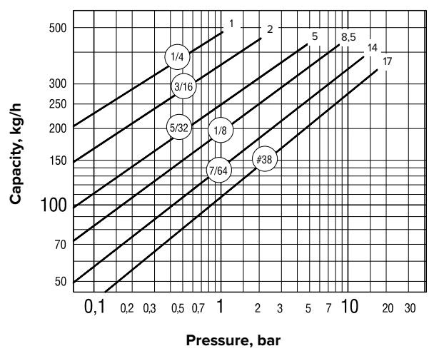
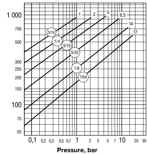
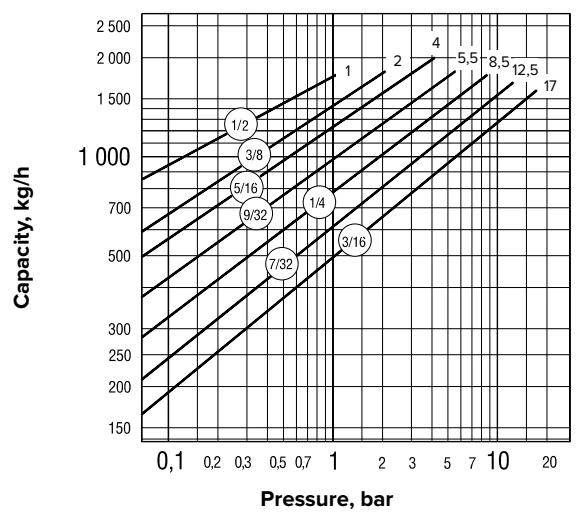
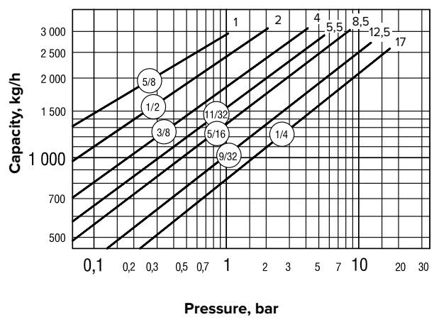
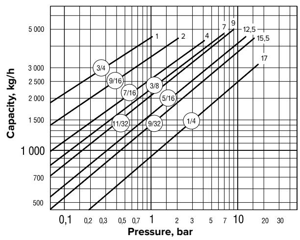
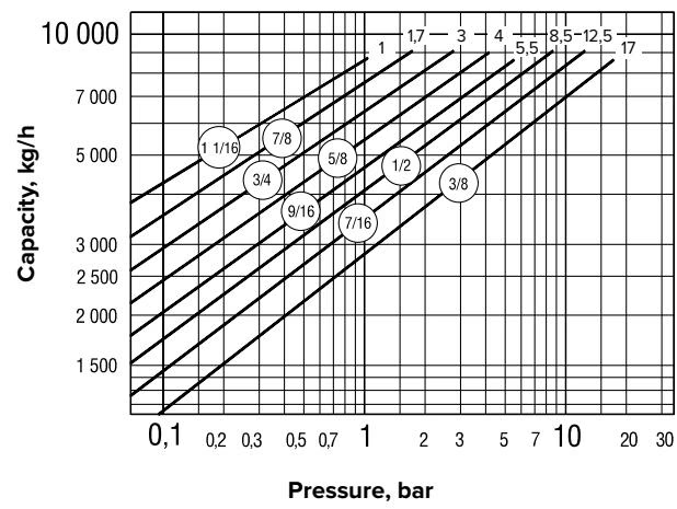
Capacity Charts