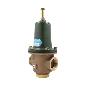
PN25

The Armstrong GD-10 and GD-10F are lightweight direct-acting diaphragm pressure reducing valves for air and non-corrosive gases, featuring zinc or aluminum bodies.
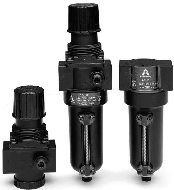
The Armstrong GD-10 and GD-10F are lightweight direct-acting diaphragm valves used primarily for pneumatic tool air supply and non-hazardous gas regulation. Screwed connections make it easy to support in position without external sensing lines or other parts. Zinc or aluminum bodies eliminate rust and scale. The plug, seat, and diaphragm are renewable in-line, and quick adjustments can be made externally with a locking handle. A quarter-inch pressure gauge connection is standard, and all units are capable of tight shutoff for dead-end service.
The GD-10 is available in sizes 1/4" - 2". Highly efficient Model AF-10 air filters with zinc or aluminum bodies are used to remove liquids and solid particles from compressed air. The AF-10 is available in sizes 1/4" - 1".
| GD-10/GD-10F/AF-10 Specifications | ||||||||||
| Model | Application | Inlet Pres. psig (bar) | Reduced Pressure psig (bar) | Min. Differ. psig (bar) | Max. Temp. °F (°C) | Materials | ||||
| Body in (mm) | Bowl | Main Valve in (mm) | Valve Plug in (mm) | Diaphragm | ||||||
| GD-10 | Air and Other Non-Corrosive Gases | 15 - 300 (1 - 20) | 5 - 125 (.34 - 8.6) | 7 (.48) | 175 (79) | Zinc 1/4, 3/8, 1/2, 3/4 (6, 9, 15, 20) Aluminum 1 - 2 (25 - 50) | — | Zinc 1/4, 3/8, 1/2, 3/4 (6, 9, 15, 20) Aluminum 1 - 2 (25 - 50) | Brass 1/4, 3/8, 1/2, 3/4 (6, 9, 15, 20) Nylon 1 - 2 (25 - 50) | Nitrile |
| GD-10F | 15 - 250 (1 - 17) | 5 - 125 (.34 - 8.6) | 7 (.48) | Zinc | Brass | Nitrile | ||||
| AF-10 | 0 - 250 (0 - 17) | — | — | Zinc 1/4, 3/8, 1/2, 3/4 (6, 9, 15, 20) Aluminum 1 (25) | — | — | — | |||
| Symbol | Connection Size | |||||||||||
| in | mm | in | mm | in | mm | in | mm | in | mm | in | mm | |
| 1/4 | 8 | 3/8 | 10 | 1/2 | 15 | 3/4 | 20 | 1, 1-1/4, 1-1/2 | 25, 32, 40 | 2 | 50 | |
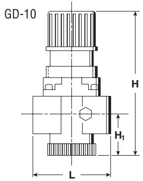
| L | 2-5/8 | 67 | 2-5/8 | 67 | 2-5/8 | 67 | 3-1/2 | 98 | 4-1/4 | 108 | 6 | 152 |
| H | 5-3/8 | 136 | 5-3/8 | 136 | 5-3/8 | 136 | 5-7/8 | 149 | 7-1/8 | 181 | 9-3/4 | 248 |
| H1 | 1-1/2 | 38 | 1-1/2 | 38 | 1-1/2 | 38 | 1-1/2 | 38 | 2-3/8 | 60 | 3-9/16 | 90 |
| Wt, lb (kg) | 1-1/2 (.7) | 1-1/2 (.7) | 1-1/2 (.7) | 2 (.9) | 3 (1.4) | 10 (4.5) | ||||||
| Cv | 1.4 | 2.6 | 5.8 | 43 | ||||||||
INFO
** 2" (50 mm) GD-10 valve maximum inlet pressure is 425 psi (30 bar). † GD-10F has a maximum inlet pressure of 250 psi (17 bar).
| GD-10F Dimensions and Weights | ||||||||
| Symbol | Connection Size | |||||||
| in | mm | in | mm | in | mm | in | mm | |
| 1/4 | 8 | 3/8 | 10 | 1/2 | 15 | 3/4 | 20 | |
| L | 2-3/4 | 70 | 2-3/4 | 70 | 2-3/4 | 70 | 3-7/8 | 98 |
| H | 9-3/8 | 238 | 9-3/8 | 238 | 9-3/8 | 238 | 10-7/8 | 276 |
| H1 | 5-3/4 | 146 | 5-3/4 | 146 | 5-3/4 | 146 | 6-3/8 | 162 |
| Wt, lb (kg) | 2-1/2 (1.2) | 2-1/2 (1.2) | 4-1/2 (2.0) | 4-1/2 (2.0) | ||||
| Cv | 1.4 | 2.6 | ||||||
| AF-10 Dimensions and Weights | ||||||||||
| Symbol | Connection Size | |||||||||
| in | mm | in | mm | in | mm | in | mm | in | mm | |
| 1/4 | 8 | 3/8 | 10 | 1/2 | 15 | 3/4 | 20 | 1 | 25 | |
| L | 2-3/4 | 70 | 2-3/4 | 70 | 2-3/4 | 70 | 3-7/8 | 98 | 4-3/4 | 121 |
| H | 6-3/8 | 162 | 6-3/8 | 162 | 6-3/8 | 162 | 7 | 178 | 11-3/8 | 289 |
| H1 | 5-3/4 | 146 | 5-3/4 | 146 | 5-3/4 | 146 | 6-3/8 | 162 | 10 | 254 |
| Wt, lb (kg) | 2 (.9) | 3 (1.4) | ||||||||
| GD-10/GD-10F Capacities—Air | ||||||||||||
| scfm | m³/hr | |||||||||||
| Inlet | Outlet | Connection Size | Inlet | Outlet | Connection Size | |||||||
| in | mm | |||||||||||
| psig | 1/4, 3/8, 1/2 | 3/4 | 1*, 1-1/4, 1-1/2 | 2** | bar | 8, 10, 15 | 20 | 25*, 32, 40 | 50** | |||
| 15 | 8 | 19 | 35 | 78 | 580 | 1.0 | 0.6 | 32 | 60 | 133 | 985 | |
| 30 | 23 | 24 | 44 | 98 | 727 | 2.0 | 1.6 | 40 | 75 | 167 | 1,235 | |
| 15 | 33 | 61 | 136 | 1,011 | 1.0 | 56 | 104 | 232 | 1,718 | |||
| 5 - 7 | 38 | 70 | 157 | 1,166 | .34 - 48 | 64 | 120 | 267 | 1,981 | |||
| 40 | 33 | 26 | 49 | 109 | 810 | 2.8 | 2.3 | 45 | 83 | 186 | 1,377 | |
| 20 | 42 | 77 | 173 | 1,280 | 1.4 | 71 | 131 | 293 | 2,174 | |||
| 5 - 12 | 46 | 86 | 192 | 1,427 | .34 - .83 | 79 | 147 | 327 | 2,424 | |||
| 50 | 40 | 34 | 63 | 141 | 1,046 | 3.4 | 2.8 | 58 | 107 | 240 | 1,777 | |
| 30 | 46 | 86 | 191 | 1,416 | 2.1 | 78 | 145 | 324 | 2,405 | |||
| 5 - 17 | 55 | 102 | 228 | 1,687 | .34 - 1.17 | 93 | 173 | 387 | 2,867 | |||
| 75 | 60 | 49 | 91 | 203 | 1,503 | 5.2 | 4.1 | 83 | 154 | 344 | 2,553 | |
| 45 | 66 | 123 | 273 | 2,026 | 3.1 | 112 | 208 | 464 | 3,442 | |||
| 7 - 30 | 76 | 141 | 316 | 2,339 | .48 - 2.1 | 129 | 240 | 536 | 3,975 | |||
| 100 | 80 | 64 | 118 | 264 | 1,958 | 6.9 | 5.5 | 108 | 201 | 449 | 3,327 | |
| 60 | 86 | 159 | 355 | 2,634 | 4.1 | 146 | 271 | 604 | 4,475 | |||
| 10 - 42 | 97 | 181 | 403 | 2,991 | .69 - 2.9 | 165 | 307 | 686 | 5,082 | |||
| 125 | 100 | 79 | 146 | 326 | 2,413 | 8.6 | 6.9 | 134 | 248 | 553 | 4,101 | |
| 75 | 106 | 196 | 437 | 3,241 | 5.2 | 179 | 333 | 743 | 5,507 | |||
| 13 - 55 | 119 | 220 | 491 | 3,643 | .89 - 3.8 | 202 | 374 | 835 | 6,190 | |||
| 150 | 120 | 93 | 173 | 387 | 2,868 | 10.3 | 8.3 | 159 | 295 | 657 | 4,873 | |
| 85 | 129 | 240 | 535 | 3,967 | 5.9 | 219 | 408 | 909 | 6,741 | |||
| 15 - 67 | 140 | 260 | 579 | 4,295 | 1.03 - 4.6 | 238 | 441 | 984 | 7,298 | |||
| 175 | 125 | 126 | 235 | 524 | 3,884 | 12.1 | 8.6 | 215 | 399 | 890 | 6,599 | |
| 100 | 149 | 276 | 617 | 4,573 | 6.9 | 253 | 470 | 1,048 | 7,769 | |||
| 18 - 80 | 161 | 299 | 667 | 4,947 | 1.24 - 5.5 | 274 | 508 | 1,134 | 8,405 | |||
| 200 | 125 | 161 | 298 | 666 | 4,934 | 13.8 | 8.6 | 273 | 507 | 1,131 | 8,383 | |
| 20 - 92 | 182 | 339 | 755 | 5,599 | 1.38 - 6.3 | 310 | 575 | 1,283 | 9,513 | |||
| 250† | 25 - 125 | 225 | 417 | 931 | 6,903 | 17.2† | 1.7 - 8.6 | 382 | 709 | 1,582 | 11,729 | |
| 300 | 30 - 125 | 267 | 496 | 1,107 | 8,207 | 20.0 | 2.1 - 8.6 | 454 | 843 | 1,881 | 13,944 | |
| 350** | 35 - 125 | — | — | — | 9,511 | 24.1** | 2.4 - 8.6 | — | — | — | 16,159 | |
| 425** | 43 - 125 | — | — | — | 11,467 | 29.3** | 3.0 - 8.6 | — | — | — | 19,482 | |
INFO
GD-10F is not available above 3/4" (20 mm).
Typical Piping For Air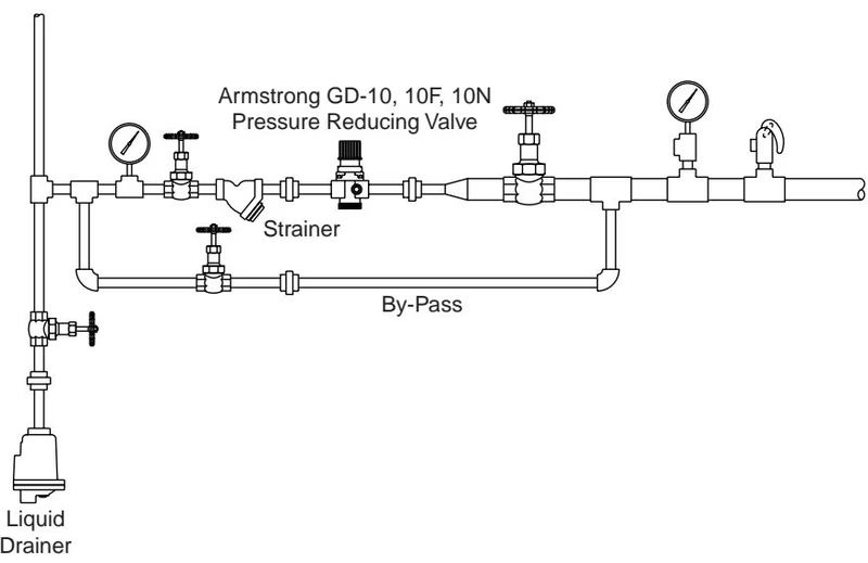
Typical Piping For Steam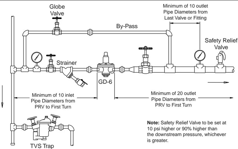
WARNING
Improper adjustment of the pressure reducing valve may cause hunting, scale problems, etc., and damage to the valve itself.
Adjust the valve as follows:
| Problem | Cause | Solution |
|---|---|---|
| The desired pressure cannot be obtained | The inlet pressure is not suitable. | Change the pressure to the appropriate level. |
| The valve size is excessively smaller than what is required. | Change to the appropriate size. | |
| The inlet strainer is clogged by a foreign substance. | Disassemble and clean the strainer. | |
| The pressure gauge is out of order. | Replace the gauge. | |
| The outlet pressure rises higher than the specified pressure. | The valve and the valve seat are clogged by a foreign substance. | Disassemble and clean the valve seat. |
| The "O" ring is damaged. | Replace the "O" Ring. |
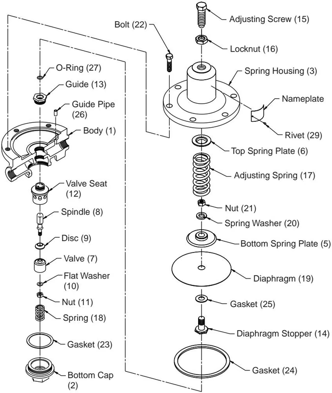
Disassembly of Body Turn the valve guide counterclockwise and remove it from the body. Pull out and remove the valve and spring.
Disassembly of Diaphragm
Notes To Reassemble
Explore similar products in our catalog