


PN25

Armstrong OB-2000PT is a high-performance, diaphragm-operated externally piloted pressure and temperature combination regulator for steam service.
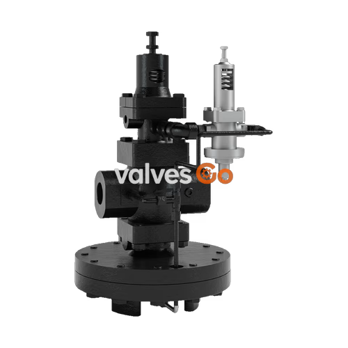
Armstrong OB-2000PT is a high-performance, diaphragm-operated externally piloted pressure and temperature combination regulator. It is designed for large capacity applications such as heat exchangers, steam coils, steam dryers, plating tanks, and parts washers.
It is used in applications where maximum pressure should be limited and the temperature of the heated medium is controlled using a single seated main valve. The temperature pilot and capillary unit can be easily disconnected, making repairs or temperature range changes quick and easy. It is available in sizes 1/2" through 6" and with a choice of four spring ranges, six temperature ranges, and three capillary lengths.
| Application | Inlet Pressure psig (bar) | Minimum Differ. Pressure psig (bar) | Reduced Pressure & Spring Color psig (bar) | Temperature Ranges °F (°C) | Temperature Accuracy °F (°C) | Capillary Lengths feet (meters) |
|---|---|---|---|---|---|---|
| Steam | NPT: 15 - 300 (1 - 20) 150 lb Flanged: 15 - 185 (1 - 13) 300 lb Flanged: 15 - 300 (1 - 20) | 7 (.48) | 1.5 - 3 (.10 - .21) Yellow 3 - 21 (.21 - 1.4) Yellow 15 - 200 (1.0 - 13.8) Green | 18 - 59 (-8 - 15) 50 - 97 (10 - 36) 86 - 144 (30 - 62) 131 - 201 (55 - 94) 176 - 260 (80 - 127) 239 - 361 (115 - 183) | ±2 (±1) From Set Point | 6-1/2 (2)* 9-1/2 (3) 16-1/2 (5) |
*Standard length.
| Capillary Material | Capillary Temperature Ranges °F (°C) | Bulb Material | Bulb Connection | Thermal Well Material | Thermal Well Connection |
|---|---|---|---|---|---|
| Copper Capillary Tube With 304 Stainless Steel Armor Shield | 18 - 59 (-8 - 15) 50 - 97 (10 - 36) 86 - 144 (30 - 62) 131 - 201 (55 - 94) 176 - 260 (80 - 127) 239 - 361 (115 - 183) | Nickel Plated Copper Bulb | 3/4" (20 mm) NPT | Brass* 304 Stainless Steel* | 1" (25 mm) NPT |
*Standard. Other material available upon request.
WARNING
Capillary can withstand a maximum of 36°F (20°C) above rated range. If desired set temperature is in temperature range overlap, select lower range.
| Component | Body Material | Valve & Seat Material | Maximum Temperature °F (°C) |
|---|---|---|---|
| Main Valve | Ductile Iron ASTM A536 | Stainless Steel AISI 420 | 450 (232) |
| Temperature Pilot Valve | Bronze ASTM B584 | Stainless Steel AISI 420 | 450 (232) |
| Pressure Pilot | Ductile Iron ASTM A536 | Stainless Steel AISI 420 | 450 (232) |
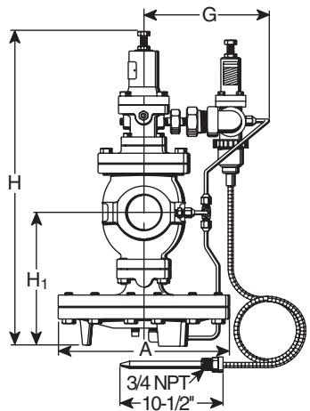
| Size in (mm) | Face-to-Face NPT in (mm) | Face-to-Face 150# in (mm) | Face-to-Face 300# in (mm) | H in (mm) | H1 in (mm) | A in (mm) | G in (mm) | Weight NPT lb (kg) | Weight 150# lb (kg) | Weight 300# lb (kg) | Cv |
|---|---|---|---|---|---|---|---|---|---|---|---|
| 1/2 (15) | 5-15/16 (150) | 5-9/16 (141) | 5-3/4 (147) | 15-3/4 (398) | 6-3/4 (170) | 7-15/16 (200) | 6-1/2 (166) | 47 (22) | 49 (23) | 55 (25) | 5.0 |
| 3/4 (20) | 5-15/16 (150) | 5-1/2 (140) | 5-3/4 (147) | 15-3/4 (398) | 6-3/4 (170) | 7-15/16 (200) | 6-1/2 (166) | 47 (22) | 49 (23) | 55 (25) | 7.2 |
| 1 (25) | 6-15/16 (160) | 5-3/4 (147) | 6-1/4 (159) | 15-15/16 (404) | 6-15/16 (175) | 8-15/16 (226) | 7 (178) | 57 (26) | 59 (28) | 64 (29) | 10.9 |
| 1-1/4 (32) | 7-1/8 (180) | 6-1/2 (166) | 7-1/16 (179) | 17-1/8 (434) | 7-5/8 (192) | 8-15/16 (226) | 7-1/4 (185) | 67 (31) | 69 (31) | 74 (34) | 14.3 |
| 1-1/2 (40) | 7-1/8 (180) | 7-7/16 (189) | 7-15/16 (202) | 17-1/8 (434) | 7-5/8 (192) | 8-15/16 (226) | 7-1/4 (185) | 67 (31) | 69 (31) | 75 (34) | 18.8 |
| 2 (50) | 9-1/8 (230) | 8-9/16 (217) | 9-1/8 (232) | 19-5/8 (498) | 8-1/2 (216) | 10-15/16 (276) | 6-1/2 (166) | 89 (41) | 94 (43) | 100 (46) | 32 |
| 2-1/2 (65) | - | 10-15/16 (278) | 11-1/2 (292) | 21-3/4 (552) | 9-13/16 (251) | 13-13/16 (352) | 6-1/2 (166) | - | 158 (72) | 167 (76) | 60 |
| 3 (80) | - | 11-3/4 (298) | 12-7/16 (315) | 22-5/8 (575) | 10-7/16 (264) | 13-13/16 (352) | 6-1/2 (166) | - | 171 (78) | 183 (83) | 78 |
| 4 (100) | - | 13-1/2 (343) | 14-1/8 (359) | 25-15/16 (658) | 12-5/8 (321) | 15-13/16 (401) | 6-1/2 (166) | - | 263 (120) | 281 (128) | 120 |
Note: For 6” (150 mm) consult factory.
Points to Remember When Installing
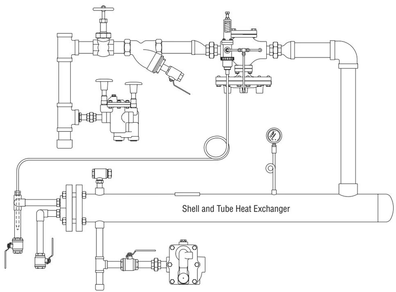
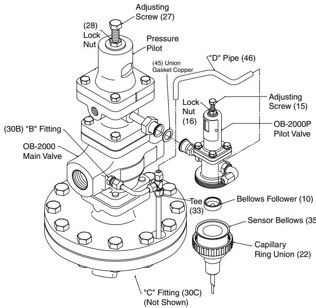
The pressure/temperature regulator will come in two (2) boxes. One box will contain an integral mount (pressure pilot mounted on the top of the main valve) main valve and the second box containing the temperature pilot with fittings which is not connected to the integral mounted valve and the capillary system.
A. Assembly
B. Installation of OB-2000PT Main Valve
C. Installation of Capillary System
INFO
Temperature control is best achieved when the delivery pressure is the lowest steam pressure capable of maintaining the desired temperature at maximum load.
DANGER
Equipment under pressure - Operating temperature > 100°C. Make sure temperature regulator is cold and pressure has been relieved before handling!
A. Disassembly of Temperature Pilot Valve
B. Disassembly of Pressure Pilot Valve
C. Disassembly of Main Valve
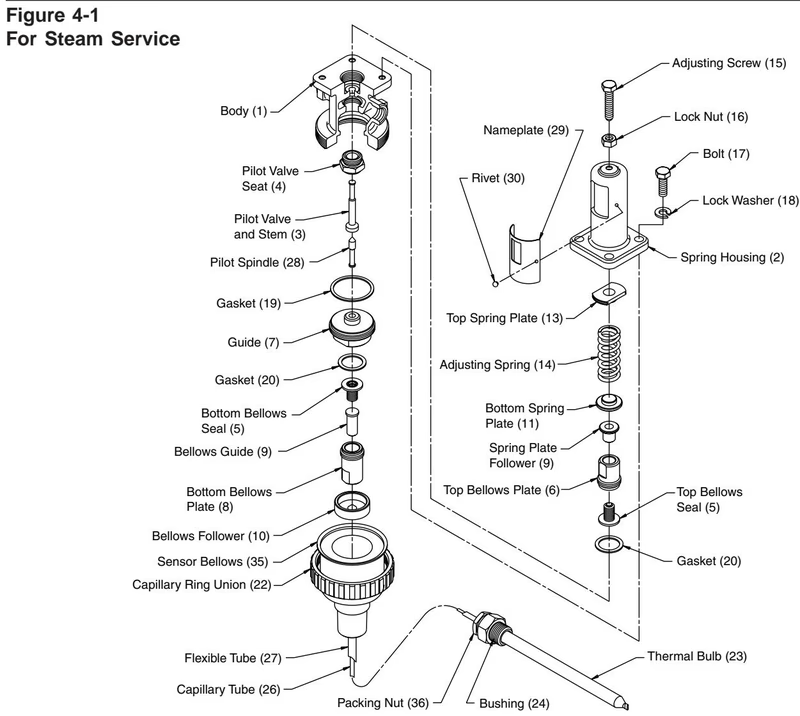
| Problem | Cause | Solution |
|---|---|---|
| Temperature Regulator does not reach desired set temperature. | Improper adjustment. | Re-adjust according to Regulating Methods. |
| Faulty steam trap draining equipment. | Check trap and correct problem. | |
| Inadequate pressure to eliminate condensate. | Re-pipe system. | |
| Bellows follower (10) was not installed. | Install bellows follower. | |
| No transfer medium applied to sensor. | Apply heat transfer paste to thermal bulb before installing in well. | |
| Incorrect capillary range. | Check label and change to correct range. | |
| Temperature rises excessively. | Improper adjustment. | Re-adjust according to Regulating Methods. |
| Dirt or scale on main valve (6) and main valve seat (7) or flawed valve and seat. | Disassemble and clean valve and seat. In case of flawed valve and seat replace them. | |
| Dirt or scale on pilot valve and stem (3), pilot valve seat (4). | Disassemble pilot and clean. | |
| Fitting orifice (30B) is blocked. | Remove and clean. | |
| Broken capillary system. | Replace capillary system. | |
| By-pass line leaks. | Repair by-pass line. | |
| Large variation between thermometer and temperature regulator setting. | Thermal bulb or thermometer are installed in wrong location. | Relocate the thermal bulb so the fluid freely flows around 3/4" of the bulb and/or relocate the thermometer closer to the thermal bulb. |
| Inlet pressure too high. | Lower inlet pressure. On low load applications, the lower the inlet pressure, the more stable the control will be. | |
| Dirt or scale on pilot valve and stem (3), guide (7) and pilot valve seat (4), main spindle (9) is dirty. | Disassemble and clean. | |
| Body gasket leaks. | Tighten bolts and replace gaskets | |
| External leak. | Broken top bellows seal (5). | Replace top bellows seal. |
Explore similar products in our catalog



