
PN25

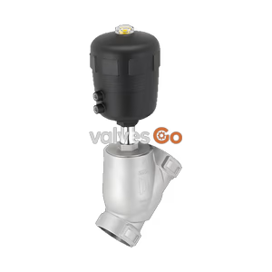
BURKERT 20001034 Type 2100 is a pneumatically operated 2/2-way angle seat valve with DN15 G 1/2 ports, stainless steel CF3M body, PTFE seal, normally closed function, and 25 bar pressure rating.
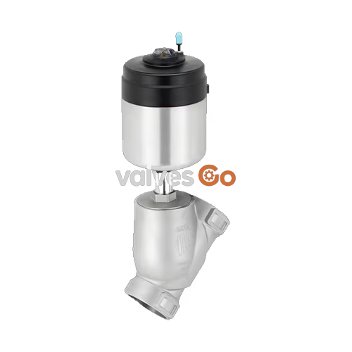
BURKERT 20001034 Type 2100 is a pneumatically operated 2/2-way angle seat valve designed for decentralized automation in demanding fluid handling processes. The valve assembly combines a precision-cast CF3M stainless steel angle seat body, an internal G 1/2 port connection with a 65 mm face-to-face installation length, and an ELEMENT series piston actuator manufactured from polyphenylene sulphide (PPS) and stainless steel. Configured with Control Function A (normally closed, spring-return) and actuator size 50 (D), this model handles water, steam, alcohols, fuels, hydraulic fluids, saline solutions, alkaline solutions, organic solvents, and neutral gases up to 25 bar operating pressure.
High stem sealing integrity and extended cycle life are maintained through a self-adjusting PTFE V-ring packing gland with spring compensation. The valve guides media below the seat, avoiding pressure surges and hydraulic shocks during closure while providing a water flow coefficient Kv of 5.3 m³/h. The device integrates pilot air channels directly into the actuator housing and holds IP67 and NEMA 4X environmental protection ratings.
Pre-Tensioned Spring Hazard
The pneumatic actuator contains a pre-tensioned mechanical spring. Opening the actuator housing presents a severe risk of injury from spring ejection. Do not open or disassemble the actuator housing under any circumstances.
Operational Pressure and Thermal Limits
Failure to comply with technical limit values can result in structural failure, seal blowout, and hot media leakage. Disconnect media pressure and vent all piping prior to performing installation or maintenance activities. Wear protective gloves when servicing systems exposed to media temperatures up to 160 °C.
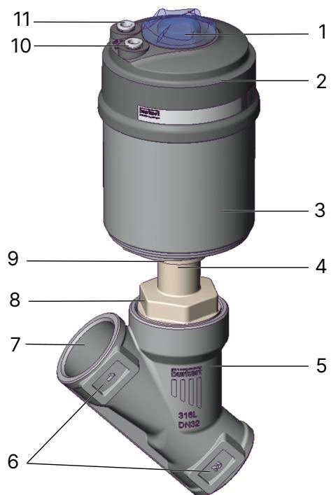
| Item | Description | Item | Description |
|---|---|---|---|
| 1 | Transparent position indicator cap | 7 | Port connection (G 1/2) |
| 2 | Actuator cover | 8 | Body connection nut |
| 3 | Actuator housing (PPS) | 9 | Actuator connection nut |
| 4 | Relief bore (leak detection) | 10 | Pilot air port 1 (supply) |
| 5 | Valve body (CF3M stainless steel) | 11 | Pilot air port 2 (exhaust / silencer) |
| 6 | Flow direction arrow marking |
Product identity and working limits are engraved on the device nameplate and cast onto the body.
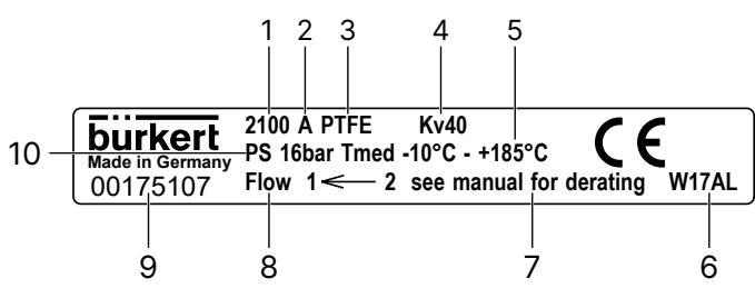
Nameplate parameters include:
BURKERT 20001034 operates under Control Function A (CFA). In its de-energized rest position, internal springs force the actuator piston downward, seating the stainless steel swivel plate and PTFE seal tightly against the valve orifice to shut off line flow.
When compressed pilot air (5.2 to 10 bar) is applied to pilot air port 1, the pneumatic piston moves upward against the spring stack, lifting the valve spindle and swivel plate into the fully open position. When port 1 vents, spring force drives the valve closed.
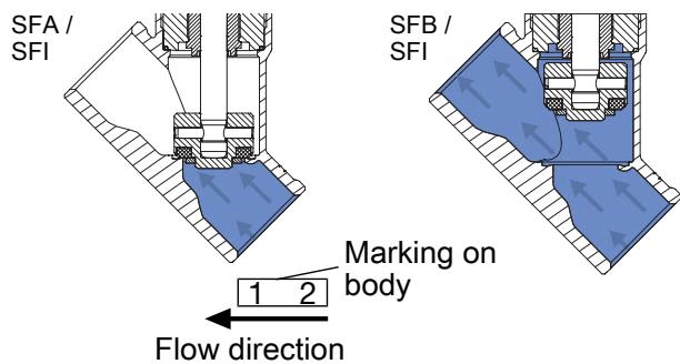
This valve utilizes flow direction below the seat exclusively. Media pressure enters underneath the swivel plate, assisting the opening stroke and preventing hydraulic water hammer in liquid installations.
Flow Direction Restriction
Valves installed with flow direction above the seat must not be used on liquid media due to severe water hammer risks. Model 20001034 is factory-configured for flow below the seat, supporting both liquid and gaseous process media.
| Parameter | Value |
|---|---|
| Valve Type | 2100 (2/2-way angle seat valve) |
| Article Number | 20001034 |
| Control Function | Control Function A (normally closed) |
| Nominal Diameter | DN15 |
| Seat Diameter | 15 mm |
| Flow Value Kv (Water) | 5.3 m³/h |
| Body Connection Thread | G 1/2 internal thread |
| Installation Face-to-Face Length | 65 mm |
| Body Material | Stainless steel CF3M |
| Valve Seat Seal | PTFE (polytetrafluoroethylene) |
| Packing Gland | PTFE V-rings with spring compensation |
| Spindle & Swivel Plate | Stainless steel 1.4401 / 1.4404 |
| Actuator Size | 50 (D), diameter 64.5 mm |
| Actuator Material | PPS housing, stainless steel trim |
| Operating Pressure Range | 0 to 25 bar |
| Minimum Pilot Pressure | 5.2 bar |
| Maximum Pilot Pressure | 10 bar |
| Medium Temperature | 0 °C to 160 °C (material rating to 230 °C) |
| Ambient Temperature | -10 °C to 60 °C |
| Storage Temperature | -20 °C to +65 °C |
| Pilot Air Connection | Push-in connector 6 mm (Interface ELEMENT) |
| Ingress Protection | IP67 (EN 60529 / IEC 60529), NEMA 4X |
| Sound Pressure Level | < 70 dB(A) |
| Approvals & Conformity | ATEX, IECEx, DVGW, DIN EN 161 compliant |
Operating pressure must be reduced at elevated media temperatures in compliance with DIN EN 12516-1 (PN25) and ASME B16.34 Class 150 pressure-temperature ratings.
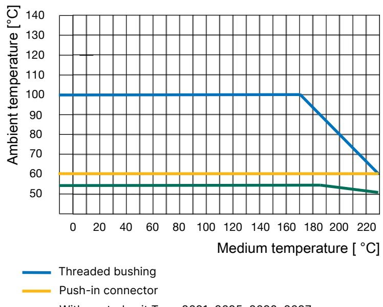
| Temperature Range [°C] | DIN EN 12516-1 PN25 [bar] | ASME B16.34 Cl. 150 [bar] | JIS B 2220 10K [bar] |
|---|---|---|---|
| -10 to +50 | 25.0 | 18.4 (at 50 °C) | 14.0 |
| 100 | 24.5 | 16.2 | 14.0 |
| 150 | 22.4 | 14.8 | 13.4 |
| 160 | 22.0 | 14.5 | 13.1 |
| 200 | 20.3 | 13.7 | 12.4 |
| 230 | 19.0 | 12.7 | 11.7 |
Mount the valve into pipeline systems with the actuator oriented upright where space permits. Ensure piping is axially aligned and free of mechanical stress, welding slag, or particulate matter.
Gas Application In-Line Strainer Requirement
For installations subject to DIN EN 161 (automatic shut-off valves for gas burners and gas appliances), fit a dirt trap upstream of the valve body. The strainer mesh must prevent penetration of a 1 mm test mandrel.
If the valve body requires welding or separate pipeline brazing, remove the actuator prior to heating the body to avoid thermal degradation of internal seals and the PPS casing.
Actuator Must Be Open During Removal and Mounting
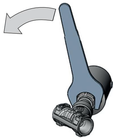
For Control Function A, the valve must be pneumatically actuated into the fully open position before loosening or tightening the body connection. Pressurizing pilot air port 1 with 5.0 bar lifts the swivel plate off the valve seat, preventing mechanical distortion of the PTFE seat face.
| Valve Size | Actuator Size | Tightening Torque [Nm] | Tolerance [Nm] |
|---|---|---|---|
| DN15 | 50 (D) | 45 | +10 / -5 |
| DN20 | 50 (D) | 50 | +10 / -5 |
| DN25 | 50 (D) | 60 | +10 / -5 |
Periodic Torque Verification
In operating environments subjected to severe pipeline vibration or medium temperatures exceeding 140 °C, the threaded body joint may loosen over extended operating periods. Regularly check and retighten the body connection nut to 45 Nm.
The pneumatic actuator can be rotated steplessly through 360° to position pilot ports and position indicators favorably within congested skids.
Connect pneumatic hoses directly into the actuator ports:
Pilot Exhaust in Corrosive Atmospheres
When installed in aggressive chemical or washdown environments, do not leave exhaust port 2 open. Route a pneumatic hose from port 2 to discharge exhaust into a neutral, unpolluted atmosphere.
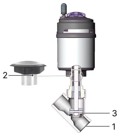
Perform regular external cleaning with a damp cloth and inspect the three critical seal boundaries shown below.
| Inspection Area | Inspection Point | Corrective Measure |
|---|---|---|
| 1 | Process pipe connections | Tighten threaded fittings or replace sealing gaskets. |
| 2 | Actuator relief bore | Replace the packing gland assembly or actuator cartridge if fluid leaks. |
| 3 | Valve seat disc & body seat | Replace the swivel plate and PTFE seal set if internal seat bypass occurs. |
| Fault Condition | Potential Root Cause | Recommended Action |
|---|---|---|
| Actuator does not switch | Pilot air connected to incorrect port | Connect pilot supply line to port 1. |
| Pilot pressure insufficient (< 5.2 bar) | Increase pilot supply pressure to 5.2–10 bar. | |
| Process line pressure exceeds rating | Reduce line pressure to match PN25 limit. | |
| Reverse pipeline flow orientation | Verify flow enters below seat according to body arrow. | |
| Valve leaks across the seat | Pilot air pressure decaying or leaking | Check pilot air line and fittings for pressure drops. |
| Particulate contamination on seat | Disassemble and install an upstream dirt trap. | |
| PTFE seat seal worn or damaged | Install a replacement swivel plate assembly. | |
| Medium leaks from relief bore | Packing gland V-rings worn | Replace the PTFE packing gland cartridge using tool 683221. |
To replace the self-adjusting packing gland cartridge without damaging the valve spindle or body neck, use the dedicated factory socket wrench.
| Spindle Diameter [mm] | Nominal Diameter DN | Width Across Flats [mm] | Article Number |
|---|---|---|---|
| 10 | 15 to 50 | 19 | 683221 |
| 14 | 32 to 80 | 21 | 683223 |
BURKERT 20001034 complies with ATEX certification EPS 18 ATEX 2 008 X and IECEx EPS 18.0007 X as non-electrical mechanical equipment (constructional safety "c"): II 2 G Ex h IIC T4...T2 Gb and II 2 D Ex h IIIC T135°C...T300°C Db.
| Temperature Class | Maximum Permissible Surface Temperature | Permissible Ambient Temperature Range | Maximum Medium Temperature |
|---|---|---|---|
| T4 | 135 °C | -40 °C to +100 °C | +125 °C |
| T3 | 200 °C | -40 °C to +130 °C | +185 °C |
| T2 | 300 °C | -40 °C to +130 °C | +285 °C |
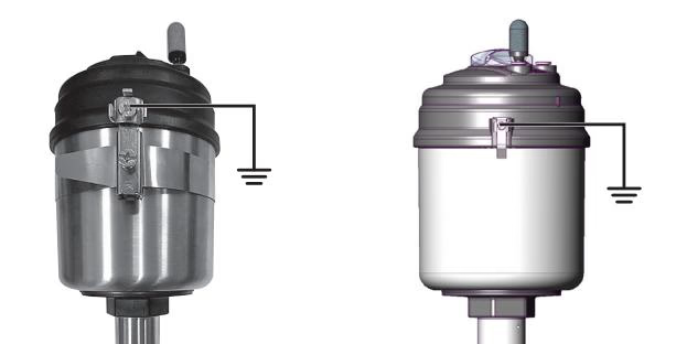
Electrostatic Discharge Hazard in Zone 1 / 21
Electrostatic charges can build up on non-conductive surfaces, posing severe ignition risks in explosive gas or combustible dust atmospheres. Clean plastic components exclusively with a damp or anti-static cloth. Never wipe surfaces with dry materials.
Explore similar products in our catalog