
Transit-Time Ultrasonic

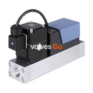
BURKERT 20031469 Type 8745 gas mass flow controller features a Type 2875 proportional valve, G 1/2 ports, EtherCAT interface, and calibrated 500 Nl/min O2 range at 6 bar inlet pressure.
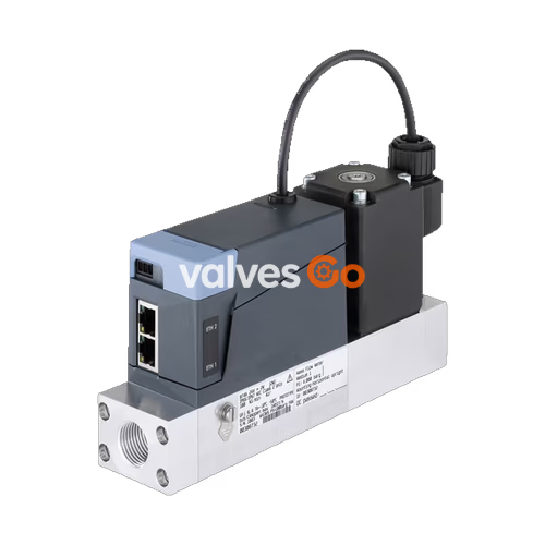
BURKERT 20031469 (Type 8745) is a gas mass flow controller engineered for closed-loop mass flow regulation in demanding industrial gas processes. Configured with a dedicated Type 2875 direct-acting electromagnetic proportional valve, this article regulates gaseous oxygen (O2) across a nominal flow range of 500 Nl/min (referenced to 1.013 bar abs and 0 °C) under an inlet operating pressure of 6.0 barg and an outlet pressure of 4.0 barg at QN. The maximum operating pressure and maximum valve pressure are rated to 8 bar. Built around an aluminium base block with G 1/2 internal threaded process connections and FKM seals, 20031469 integrates a thermal inline chip sensor operating in Constant Temperature Anemometer (CTA) mode directly in the main flow path, providing settling times below 500 ms.
Communication is established via an Industrial Ethernet EtherCAT interface using dual switched RJ45 ports. Power is supplied via a 3-pin terminal strip at 24 V DC with a typical power draw of 20.5 W (16 W valve coil) and a UL rating of 35 W. The instrument conforms to IP20 protection and operates within an ambient temperature span of -10 °C to +50 °C, supporting oxygen medium temperatures from -10 °C to +60 °C.
| Specification Parameter | Value |
|---|---|
| Article Number (MPN) | 20031469 |
| Instrument Type | 8745 |
| Operating Mode | Control (MFC) |
| Regulating Medium | Gaseous oxygen (O2) |
| Nominal Flow Rate (QN) | 500 Nl/min (re. 1.013 bar abs, 0 °C) |
| Calibration | Air with conversion parameter (higher accuracy calibration) |
| Inlet Operating Pressure (p1) | 6.0 barg |
| Outlet Pressure at QN (p2) | 4.0 barg |
| Maximum Operating / Valve Pressure | 8 bar |
| Special Execution | High differential pressure version |
| Turndown Ratio | 1:50 |
| Measuring Accuracy | ±1.5% of reading ±0.3% of full scale |
| Repeatability | ±0.1% of full scale |
| Settling Time (t95) | < 500 ms |
| Integrated Actuator | Proportional valve Type 2875, normally closed (NC) |
| Valve Orifice Size | 4.0 mm (5/32") |
| Valve Coil Size / Power | 49 x 49 mm / 16 W |
| Base Block Material | Aluminium |
| Seal Material | FKM |
| Process Connection | G 1/2 internal thread (DIN ISO 228/1) |
| Installation Position | Horizontal |
| Operating Voltage | 24 V DC (±10%, residual ripple < 2%) |
| Power Consumption | 20.5 W typical (35 W UL maximum) |
| Digital Communication | EtherCAT (100 Mbit/s, CoE SDO, 8 FMMUs, 4 Sync Managers) |
| Electrical Supply Connection | 3-pin terminal strip, 3.5 mm pitch |
| Network Connection | 2x RJ45 sockets (ETH1 IN / ETH2 OUT) |
| Service Interface | büS on micro-USB port |
| Degree of Protection | IP20 (EN 60529 / IEC 60529) |
| Ambient Temperature | -10 °C to +50 °C |
| Medium Temperature | -10 °C to +60 °C (oxygen service) |
| Storage Temperature | -10 °C to +70 °C |
| Relative Humidity | Max. 95% at +55 °C, non-condensing |
BURKERT Type 8745 integrates fluidics, sensor technology, electromagnetic actuation, and digital electronics into a single modular block. The fluidic channel comprises the aluminium base block housing the thermal inline sensor and the inlet filter screen, coupled to the direct-acting proportional valve.
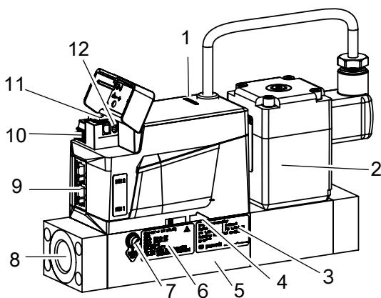
The main subassemblies visible on the Industrial Ethernet version include:
Article 20031469 employs the Bürkert Type 2875 direct-acting electromagnetic proportional control valve. The valve operates in a normally closed state when de-energised, preventing flow if control power is cut. With a 4.0 mm orifice and a 49 x 49 mm coil, the valve balances rapid seat modulation with reliable shut-off.
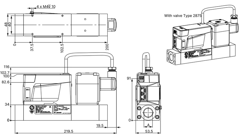
The process connections are configured as internal parallel threads compliant with DIN ISO 228/1. Connection depths and thread specifications are detailed below:
| Thread Standard | Nominal Thread Size | Thread Depth [mm] |
|---|---|---|
| DIN ISO 228/1 | G 1/4 | 12 |
| ASME / ANSI B 1.20.1 | NPT 1/4 | 11 |
| DIN ISO 228/1 | G 3/8 | 12 |
| ASME / ANSI B 1.20.1 | NPT 3/8 | 11 |
| DIN ISO 228/1 (Current Unit) | G 1/2 | 15 |
| ASME / ANSI B 1.20.1 | NPT 1/2 | 14 |
| DIN ISO 228/1 | G 3/4 | 16 |
| ASME / ANSI B 1.20.1 | NPT 3/4 | 15 |
INFO
For base block sizes supporting nominal flow rates above 1500 Nl/min (base block A3), the overall physical body length increases by 30 mm. Article 20031469 operates at 500 Nl/min with base block A1/A2 dimensions and G 1/2 connections.
The Industrial Ethernet version separates DC power input from fieldbus communication lines. A 3-pin terminal strip provides 24 V DC power and DGND, alongside a dedicated functional ground terminal.
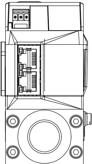
| Terminal Pin | Designation | Functional Description |
|---|---|---|
| 1 | FE | Functional earth (cable screen connection) |
| 2 | DGND | Digital ground / power supply negative pole |
| 3 | +24 V DC | Operating voltage (+24 V === ±10%, residual ripple < 2%) |
Both RJ45 female ports adhere to standard Industrial Ethernet 100BASE-TX pinout:
| RJ45 Pin | Signal Designation | Assignment Description |
|---|---|---|
| 1 | TX+ | Transmit Data + |
| 2 | TX- | Transmit Data - |
| 3 | RX+ | Receive Data + |
| 4 | N.C. | Not connected |
| 5 | N.C. | Not connected |
| 6 | RX- | Receive Data - |
| 7 | N.C. | Not connected |
| 8 | N.C. | Not connected |
| Plug Shield / Housing | FE | Functional earth via plug casing |
EtherCAT Port Routing
When using the EtherCAT protocol, insert the incoming cable from the master PLC into socket ETH1 (EtherCAT IN) and connect the outgoing cable to subsequent network nodes into socket ETH2 (EtherCAT OUT).
Functional Earth and Power Limits
To prevent electrostatic charge accumulation in gaseous oxygen processes, the housing must be bonded to functional earth using the external M4 grounding screw with a minimum conductor cross-section matching the power lead. Tighten the M4 grounding screw to 1.8 to 2.0 N·m. Operating voltage must maintain residual ripple below 2% to ensure control-loop stability.
Flow metering is based on thermal anemometry operating in Constant Temperature Anemometer (CTA) mode. The sensor incorporates two temperature-dependent resistive elements positioned directly in the gas stream and three complementary bridge resistors located outside the wetted channel.
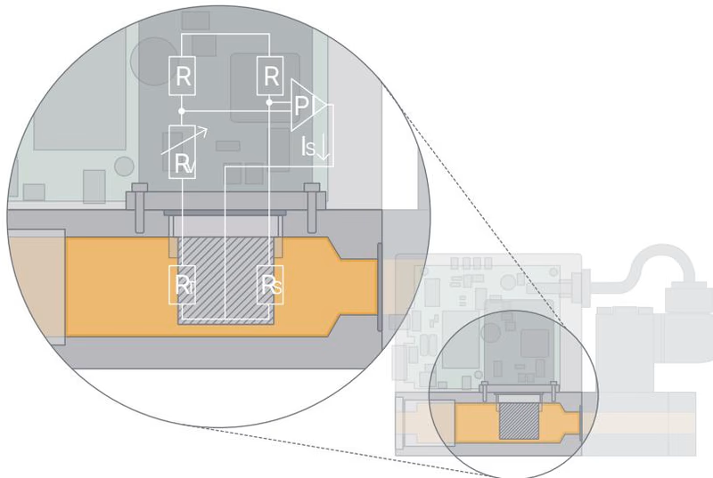
Within the bridge circuit, resistor R1 measures the instantaneous fluid temperature. Resistor R2, a low-ohmic heating element, is continuously powered to maintain a defined excess temperature relative to the gas. The heating current required to maintain this delta represents the heat dissipated by gas molecules passing the chip, forming the primary mass-flow signal. Internal flow conditioners and factory calibration with high-precision gas standards convert this primary variable into calibrated mass flow units.
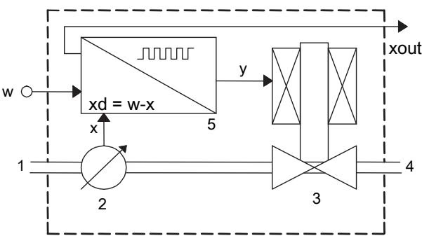
In closed-loop operation:
Parameter setting, diagnostic monitoring, and firmware servicing are handled via the Bürkert Communicator software (Type 8920) connected to the büS service micro-USB interface via the USB-büS interface set (article number 772551).
Sensor > Diagnostics > Start zero point adjustment.Commissioning Procedure
Flush Mode Restriction
Opening the integrated proportional valve completely (100% stroke) causes internal coil heating. To prevent device damage, do not operate the valve fully open in flush mode continuously for more than 10 minutes.
When operated with clean, dry gases compliant with ISO 8573-1 (Class 2 particles ≤ 1 µm, Class 2 density ≤ 1 mg/m³, Class 4 dew point ≤ +3 °C, Class 1 oil ≤ 0.01 mg/m³), Type 8745 requires no periodic internal overhaul. However, the stainless steel mesh filter in the gas inlet must be inspected regularly.
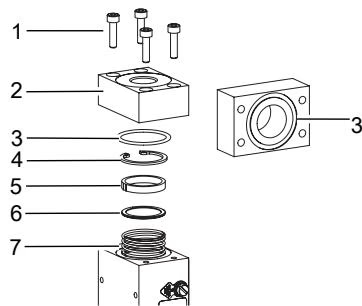
The front LED displays device diagnostics compliant with NAMUR NE107 recommendations. If multiple diagnostic events coincide, the colour corresponding to the highest priority alert is shown.
| LED Colour | Code | NAMUR Status Signal | Description and Operational Impact |
|---|---|---|---|
| Red | 5 | Failure | Critical fault in device, sensor, or supply. Normal operation interrupted. |
| Orange | 4 | Function check | Temporary maintenance active (Autotune running or calibration procedure in progress). |
| Yellow | 3 | Out of specification | Environmental, thermal, or pressure parameters outside limits; valve stroke saturated near 100%. |
| Blue | 2 | Maintenance required | Operational, but routine servicing or memory check is required. |
| Green | 1 | Diagnosis active | Device running faultlessly with active background self-diagnostics. |
| White | 0 | Diagnosis passive | Power applied; self-diagnostic monitoring inactive. |
| Observed Symptom | Probable Cause | Corrective Measure |
|---|---|---|
| Red LED lit continuously | Operating voltage outside tolerance or hardware defect | Check 24 V DC supply and ripple; contact manufacturer if voltage is nominal. |
| Red LED after Autotune | Autotune aborted or medium flow stopped | Verify gas pressure is present; confirm medium flow and restart Autotune. |
| Yellow LED lit | Temperature or voltage out of limits; set-point not reached | Check ambient/medium temperatures; increase inlet pressure or decrease outlet backpressure. |
| Unstable measured flow | Unbonded functional earth or excessive power supply ripple | Connect FE grounding conductor; verify power supply residual ripple is < 2%. |
| Medium flows at 0% set-point | Line pressure exceeds maximum shut-off rating or foreign matter in seat | Verify inlet pressure does not exceed 8 bar; inspect and clean inlet mesh filter. |
| Replacement unit adopts no data | Mismatched article numbers or corrupted memory card | Ensure replacement instrument carries article number 20031469; check card insertion. |
| Component Description | Technical Characteristics | Article Number |
|---|---|---|
| USB-büS Interface Set 2 (Type 8923) | Includes büS stick, M12 connection cable, micro-USB cable, Y-distributor (cable length 0.7 m) | 772551 |
| Phoenix Class 2 Power Supply Unit (Type 1573) | 85 to 240 V AC / 24 V DC, 1.25 A, NEC Class 2 (UL 1310) | 772438 |
| DIN Rail Power Supply Unit (Type 1573) | 100 to 240 V AC / 24 V DC, 1 A, NEC Class 2 (UL 1310) | 772361 |
| DIN Rail Power Supply Unit (Type 1573) | 100 to 240 V AC / 24 V DC, 2 A, NEC Class 2 (UL 1310) | 772362 |
| DIN Rail Power Supply Unit (Type 1573) | 100 to 240 V AC / 24 V DC, 4 A | 772363 |
| Configuration Memory Card | Device-specific dataset backup and transfer module | On request |
| Stainless Steel Compression Fitting | G 1/4 to 6 mm OD pipe | 901538 |
| Stainless Steel Compression Fitting | G 1/4 to 8 mm OD pipe | 901540 |
| Stainless Steel Compression Fitting | G 1/4 to 1/4" OD pipe | 901551 |
| Stainless Steel Compression Fitting | G 1/4 to 3/8" OD pipe | 901553 |
| Copper Gasket (1 pc) | For G 1/4 compression fitting sealing | 901575 |
| Steel/Rubber Composite Seal (1 pc) | For G 1/4 compression fitting sealing | 901579 |
| Bürkert Communicator Software | Parameter configuration and diagnostic tool (Type 8920) | Free download |
Explore similar products in our catalog