


PN25

Burkert 20051681 Type 2000 is a pneumatically operated 2/2-way angle seat valve with DN 25 welded connections, stainless steel body, PTFE seal, normally closed function A, and 0 to 25 bar operating pressure.
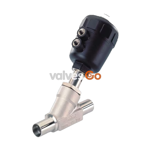
Burkert 20051681 Type 2000 is an externally piloted 2/2-way angle seat valve engineered for shut-off operations in industrial process automation. Configured with a DN 25 nominal orifice, DIN 11850 Series 2 / DIN 11866 Series A welded pipe connections (29 mm outer diameter × 1.5 mm wall thickness), and an investment-cast CF3M stainless steel body, the valve delivers a water Kv flow coefficient of 19 m³/h. A size 80 mm (F) polyamide (PA) pneumatic piston actuator drives the internal spindle, providing control function A (normally closed in rest position by internal spring force). Burkert 20051681 is rated for fluid operating pressures from 0 to 25 bar(g), medium temperatures from -40 °C to +185 °C, and pilot air pressures from 5.0 to 10.0 bar(g).
With CIP and SIP cleaning capability, IP67 enclosure protection, and a maintenance-free, self-adjusting PTFE V-ring spindle packing gland with spring compensation, Burkert 20051681 controls liquid and gaseous media including steam, water, alcohols, oils, fuels, hydraulic fluids, saline solutions, lyes, organic solvents, and neutral gases. The flow path enters below the valve seat, utilizing fluid pressure to assist opening while eliminating water hammer surges during closing.
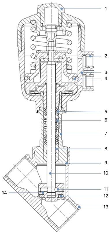
Burkert Type 2000 angle seat valves feature a flow-optimized 2-way body design combined with a linear piston actuator. The materials of construction for the CF3M stainless steel welded body variant with PA actuator are summarized below:
| Item No. | Element | Material (CF3M Stainless Steel Body with PA Actuator) |
|---|---|---|
| 1 | Transparent Cover | Polycarbonate (PC) |
| 2 | Pilot Air Ports | Stainless steel 1.4305 |
| 3 | Actuator Housing | Polyamide (PA) |
| 4 | Piston Seal | Nitrile butadiene rubber (NBR) |
| 5 | Packing Gland | Filled PTFE V-rings with spring compensation |
| 6 | Springs | Stainless steel 1.4310 |
| 7 | Tube | Stainless steel CF3M |
| 8 | Wiper | Filled PTFE |
| 9 | Body Seal | Graphite (PTFE optional) |
| 10 | Spindle | Stainless steel 1.4401 / 1.4404 |
| 11 | Pin | Stainless steel 1.4401 / 1.4404 |
| 12 | Seat Seal | Polytetrafluoroethylene (PTFE) |
| 13 | Valve Body | Cast stainless steel CF3M (316L equivalent) |
| 14 | Swivel Plate | Stainless steel CF3M / 1.4401 / 1.4404 |
Burkert 20051681 operates under Control Function A (CF A): 2/2-way, normally closed in rest position by spring force.
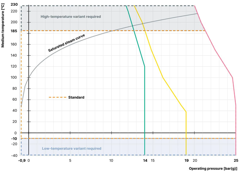
Burkert 20051681 conforms to pressure equipment standard DIN EN 12516-1 PN25 and ASME B16.34 Class 150. Maximum permissible operating pressure decreases with increasing fluid temperature as defined by DIN EN 12516-1:
| Temperature [°C] | Permissible Working Pressure PN25 [bar(g)] | Class 150 Limit [bar(g)] |
|---|---|---|
| -10 to +50 | 25.0 | 18.4 |
| 100 | 24.5 | 16.2 |
| 150 | 22.4 | 14.8 |
| 185 (Max. for PA actuator) | ~21.0 | ~14.0 |
| 200 | 20.3 | 13.7 |
| 230 | 19.0 | 12.7 |
Ambient Temperature Limits for Polyamide (PA) Actuators
For actuator sizes 40, 50, and 63 with PA housings, ambient temperature is limited to +60 °C at fluid temperatures up to +185 °C. For the size 80 (F) actuator, continuous ambient temperature must remain between -40 °C and +60 °C. Storage temperature is rated from -20 °C to +65 °C.
Fluid parameters for Type 2000 valves with welded connections according to DIN 11850 Series 2 / DIN 11866 Series A / DIN EN 10357 Series A under flow direction below the seat (CF A, normally closed):
| Port Size DN | Seat Size [mm] | Actuator Size Ø [mm] | Water Kv [m³/h] | Min. Pilot Pressure [bar(g)] | Max. Operating Pressure PTFE [bar(g)] | Max. Operating Pressure PEEK [bar(g)] |
|---|---|---|---|---|---|---|
| 10 | 15 | 40 (C) | 2.5 | 4.0 | 15.0 | — |
| 10 | 15 | 50 (D) | 2.5 | 4.1 | 16.0 | — |
| 10 | 15 | 63 (E) | 2.5 | 4.5 | 25.0 | 25.0 |
| 15 | 15 | 40 (C) | 4.7 | 4.0 | 15.0 | — |
| 15 | 15 | 50 (D) | 5.0 | 4.1 | 16.0 | — |
| 15 | 15 | 63 (E) | 5.4 | 4.5 | 25.0 | 25.0 |
| 20 | 20 | 40 (C) | 8.4 | 4.0 | 6.5 | — |
| 20 | 20 | 50 (D) | 10.0 | 4.1 | 11.0 | — |
| 20 | 20 | 63 (E) | 11.0 | 4.5 | 20.0 | 16.0 |
| 20 | 20 | 80 (F) | 11.0 | 5.0 | 25.0 | 25.0 |
| 25 (20051681) | 25 | 80 (F) | 19.0 | 5.0 | 25.0 | 21.0 |
| 25 | 25 | 50 (D) | 14.0 | 4.1 | 5.2 | — |
| 25 | 25 | 63 (E) | 19.0 | 4.5 | 11.0 | — |
| 32 | 32 | 63 (E) | 26.0 | 4.5 | 6.0 | — |
| 32 | 32 | 80 (F) | 26.0 | 5.0 | 14.0 | 11.5 |
| 32 | 32 | 100 (G) | 30.0 | 4.4 | 16.0 | — |
| 32 | 32 | 125 (H) | 30.0 | 4.1 | 25.0 | 25.0 |
| 40 | 40 | 63 (E) | 33.0 | 4.5 | 4.0 | — |
| 40 | 40 | 80 (F) | 35.0 | 5.0 | 9.0 | — |
| 40 | 40 | 100 (G) | 41.0 | 4.4 | 12.5 | — |
| 40 | 40 | 125 (H) | 40.0 | 4.1 | 25.0 | 25.0 |
| 50 | 50 | 63 (E) | 44.0 | 4.5 | 2.5 | — |
| 50 | 50 | 80 (F) | 49.0 | 5.0 | 6.0 | — |
| 50 | 50 | 100 (G) | 60.0 | 4.4 | 7.2 | — |
| 50 | 50 | 125 (H) | 60.0 | 5.7 | 24.0 | 19.0 |
| 65 | 65 | 80 (F) | 74.0 | 5.0 | 3.5 | — |
| 65 | 65 | 125 (H) | 91.0 | 5.7 | 12.0 | 10.0 |
| 80 | 80 | 125 (H) | 140.0 | 5.7 | 7.5 | — |
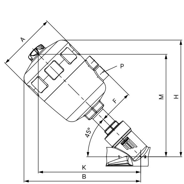
| Port Size DN | Actuator Size Ø | Ø A [mm] | B / H [mm] | K / M [mm] | Pilot Port P | BS / HS [mm] |
|---|---|---|---|---|---|---|
| 20 | 80 (F) | 101 | 195 | 171 | G 1/4 | 259 |
| 25 (20051681) | 80 (F) | 101 | 195 | 171 | G 1/4 | 259 |
| 25 | 50 (D) | 64 | 152 | 136 | G 1/4 | 223 |
| 25 | 63 (E) | 80 | 178 | 159 | G 1/4 | 242 |
| 32 | 80 (F) | 101 | 209 | 185 | G 1/4 | 273 |
| 40 | 80 (F) | 101 | 213 | 188 | G 1/4 | 277 |
Note: Dimensions B, H, K, M, HS, and BS represent maximum values and may be reduced by up to 6 mm depending on port standard.
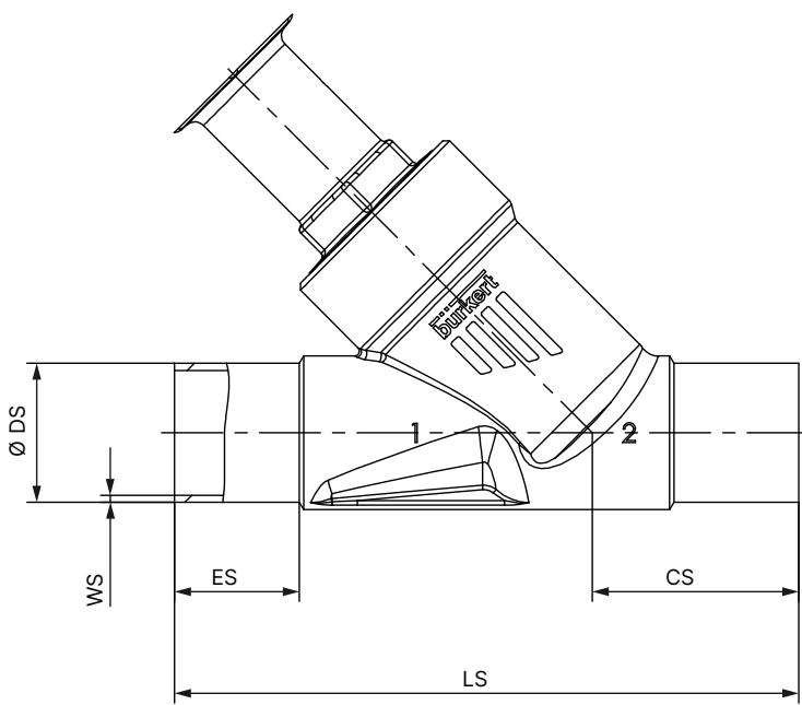
| Port DN | ES [mm] | CS [mm] | LS [mm] | Ø DS [mm] | WS [mm] |
|---|---|---|---|---|---|
| 10 | 30 | 46 | 135 | 13.0 | 1.5 |
| 15 | 19 | 34 | 100 | 19.0 | 1.5 |
| 20 | 20 | 39 | 115 | 23.0 | 1.5 |
| 25 (20051681) | 26 | 43 | 130 | 29.0 | 1.5 |
| 32 | 26 | 45 | 145 | 35.0 | 1.5 |
| 40 | 26 | 49 | 160 | 41.0 | 1.5 |
| 50 | 26 | 50 | 175 | 53.0 | 1.5 |
| 65 | 26 | 50 | 210 | 70.0 | 2.0 |
| 80 | 26 | 88.5 | 266 | 85.0 | 2.0 |
Dismount Actuator Prior to Welding
When installing valves with welded spigots, the actuator must be completely removed from the valve body before welding into the pipeline. Direct heat transfer from orbital or manual welding will destroy internal seals and the PTFE seat disc.
| Valve Size DN | Actuator Size | Tightening Torque [Nm] | Tolerance [Nm] |
|---|---|---|---|
| 15 | 40 (C), 50 (D), 63 (E) | 45 | +10 / -5 |
| 20 | 40 (C), 50 (D), 63 (E), 80 (F) | 50 | +10 / -5 |
| 25 (20051681) | 50 (D), 63 (E), 80 (F) | 60 | +10 / -5 |
| 32 | 63 (E), 80 (F), 100 (G) | 65 | +10 / -5 |
| 40 | 63 (E), 80 (F), 100 (G), 125 (H) | 65 | +10 / -5 |
| 50 | 63 (E), 80 (F), 100 (G), 125 (H) | 70 | +10 / -5 |
| 65 | 80 (F), 100 (G), 125 (H) | 70 | +10 / -5 |
The pilot air interface features a G 1/4 internal thread. For Control Function A, connect the control air line directly to the lower pilot port. The upper port remains vented to atmosphere. In aggressive or washdown atmospheres, route a pneumatic line from the upper port to an inert area.
To align the pneumatic connections with plant pipe runs, the actuator can be continuously rotated through 360°:
Avoid Sudden Media Release
Before introducing pressurized media into the pipeline, ensure the pneumatic control line is active and operating pressure limits (max. 25 bar for DN 25) match system conditions. Start-up sequence must follow:
If acoustic emission exceeds 70 dB(A) under specific operating pressures and cycling frequencies, hearing protection must be utilized by nearby personnel.
Burkert Type 2000 actuators are maintenance-free under normal operating conditions. Regular visual inspections should check for leakage across four critical zones:
| Inspection Point | Inspection Detail | Remedial Measure |
|---|---|---|
| Media Connection | Pipe weld seam tightness | Re-weld or dress process connection |
| Relief Bore | Fluid escaping from actuator weep hole | Replace spindle packing gland seal set or actuator |
| Swivel Plate / Seat | Internal seat leakage across valve | Replace valve set (swivel plate and PTFE disc) |
| Body Joint | Leakage at body-to-actuator joint | Replace graphite seal ring and re-torque to 60 Nm |
| Fault Condition | Possible Cause | Corrective Action |
|---|---|---|
| Actuator fails to stroke | Pilot line connected to upper instead of lower port | Connect pilot air to lower port for Function A |
| Pilot pressure below 5.0 bar | Increase pilot air pressure to rating (5.0–10.0 bar) | |
| Process pressure exceeds 25 bar | Verify system pressure against rating plate | |
| Flow direction reversed | Align body arrow to match pipeline flow direction | |
| Seat leakage across closed valve | Foreign particles trapped on valve seat | Install upstream strainer (1 mm mesh or finer) |
| Worn or scored PTFE seat seal | Install replacement swivel plate set | |
| Insufficient spring closing force | Verify supply is fully exhausted during closed state | |
| Fluid escaping from relief bore | Worn spindle packing V-rings | Replace spindle packing gland using assembly tools |
Burkert 20051681 integrates with modular CLASSIC series accessories for automated process control:
Explore similar products in our catalog



