


PN25

BURKERT 20064785 (Type 2012) is a pneumatically operated 2/2-way globe valve with DN 100 SMS 3008 weld ends, PA actuator, normally closed control function, 0-16 bar operating pressure, and PTFE seat seal.
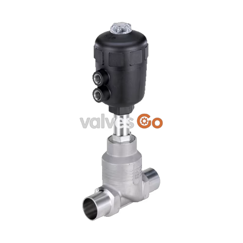
BURKERT 20064785 (Type 2012) is an externally controlled, pneumatically operated 2/2-way globe valve configured for industrial shut-off applications. The valve assembly comprises a pneumatic piston actuator with a polyamide (PA) housing and an investment cast stainless steel CF3M 2/2-way globe valve body. The process ports are SMS 3008 weld ends designed for DN 100 pipelines, having an outer diameter of 101.6 mm, an inner diameter of 97.6 mm, and a 2.0 mm wall thickness. Control function A operates as normally closed (NC) by internal spring force in the rest position, and flow enters below the seat to provide water-hammer-free operation on liquid and gaseous media.
The self-adjusting spindle packing gland utilizes spring-compensated, carbon-filled PTFE V-rings to maintain stem tightness across thermal cycles. The replaceable screwed-in valve seat works in conjunction with a PTFE seat seal, achieving leakage rate A in accordance with DIN EN 12266-1 using air as the test medium. The valve provides a nominal water flow coefficient Kv of 155 m³/h and is fully rated for Clean-In-Place (CIP) and Steam-In-Place (SIP) operations within process installations.

| Parameter | Specification |
|---|---|
| Product Identification | Article no. 20064785, Type 2012 CLASSIC |
| Nominal Diameter | DN 100 (NPS 4) |
| Port Connection Type | Weld end according to SMS 3008 |
| Port Dimensions | Outer Ø 101.6 mm, inner Ø 97.6 mm, wall thickness 2.0 mm |
| Face-to-Face Dimension (LS) | 260 mm (weld depth ES = 26 mm) |
| Operating Pressure Range | 0 to 16 bar(g) (10 bar(g) max. for PED 2014/68/EU compressible fluids Group 1) |
| Pilot Pressure Range | 4.8 to 6 bar(g) |
| Pilot Connection | G 1/4 internal thread |
| Flow Direction | Flow below seat (flow to open, closes against medium flow) |
| Flow Coefficient Kv | 155 m³/h (water at +20 °C, 1 bar pressure differential) |
| Seat Leakage Class | Leakage rate A according to DIN EN 12266-1 (PTFE seat seal, test medium air) |
| Nominal Pressure Class | PN 25 (DIN EN 1333) / Class 150 (DIN EN 1759) |
| Medium Temperature Range | -10 °C to +185 °C |
| Ambient Temperature Range | -10 °C to +50 °C (actuator size 225 mm PA) |
| Maximum Medium Viscosity | 600 mm²/s |
| Control Medium | Compressed air, neutral gases |
| Degree of Protection | IP67 |
| Explosion Protection Markings | II 2G Ex h IIC T4...T2 Gb, II 2D Ex h IIIC T135°C...T300°C Db; IECEx EPS 18.0007X |
| Conformity | Pressure Equipment Directive 2014/68/EU, Machinery Directive 2006/42/EC |
BURKERT Type 2012 utilizes a pneumatically actuated piston to translate linear motion via a stainless steel spindle to the sealing swivel plate. In control function A, integrated heavy-duty coil springs drive the spindle downward into the rest position, closing the PTFE seal against the stainless steel seat ring. Applying pilot air pressure of at least 4.8 bar(g) through the bottom pilot port (G 1/4) acts beneath the internal piston, lifting the spindle to full stroke.
Because the process fluid enters beneath the valve seat, the medium pressure acts against the underside of the swivel plate. This arrangement assists opening, avoids pressure surges, and prevents the water hammer associated with abrupt closure on liquid media.
Operational Restriction on Flow Direction
Valves configured for flow above the seat create high risk of pipe rupture and equipment damage due to water hammer when controlling liquid media. Flow above the seat must only be used on gaseous media or steam.
Explosion Protection Rating
Under ATEX certificate EPS 18 ATEX 2 008 X and IECEx EPS 18.0007X, non-electrical mechanical valve assemblies comply with category II 2G/D. Temperature classes span T4 (+135 °C surface max, medium up to +125 °C), T3 (+200 °C surface max, medium up to +185 °C), and T2 (+300 °C surface max, medium up to +285 °C). Temperature limits are restricted by the PA actuator body material specifications to +185 °C medium and +50 °C ambient.
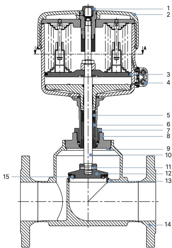
For actuator size 225 mm (L), component materials are engineered for chemical resistance and thermal cycling:
| Pos. | Component | Material |
|---|---|---|
| 1 | Transparent visual indicator cover | Polycarbonate (PC) |
| 2 | Actuator housing | Polyamide (PA) |
| 3 | Piston seal | Nitrile rubber (NBR) |
| 4 | Pilot air ports | Stainless steel 1.4305 |
| 5 | Spindle packing gland | Filled PTFE V-rings, spring-compensated |
| 6 | Compression spring | Stainless steel 1.4568 |
| 7 | Screw | Stainless steel 1.4305 |
| 8 | Threaded nipple | Stainless steel 1.4404 |
| 9 | Body seal | Graphite (PTFE optional) |
| 10 | Valve spindle | Stainless steel 1.4401 |
| 11 | Dowel pin | Stainless steel 1.4401 |
| 12 | Swivel plate | Stainless steel 1.4401 |
| 13 | Seat seal | PTFE (optional PEEK, NBR, FKM) |
| 14 | Screwed seat with O-ring | Stainless steel 1.4571, EPDM O-ring |
| 15 | Valve body | Stainless steel CF3M (cast 316L) |
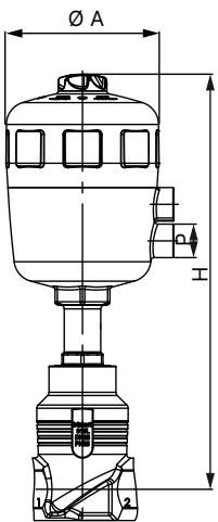
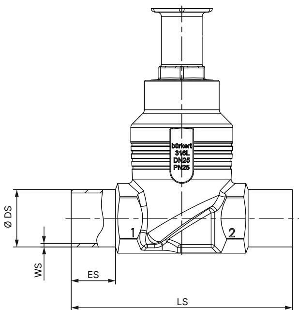
The physical envelope of article 20064785 combines the DN 100 globe valve body with the Ø 225 mm (Size L) actuator:
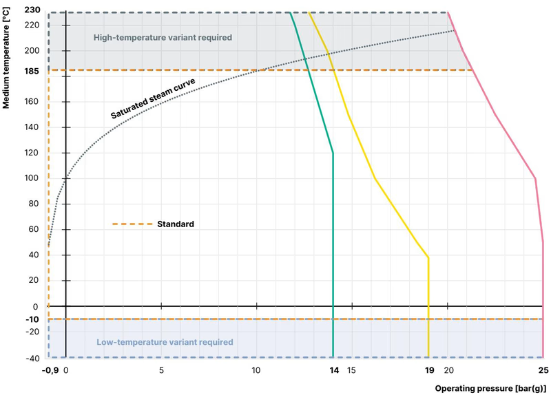
The permissible operating pressure is bounded by the nominal rating of the pipe connections according to DIN EN 12516-1 and ASME B16.34:
| Temperature Range | Maximum Operating Pressure PN 25 | Maximum Operating Pressure Class 150 |
|---|---|---|
| -10 °C to +50 °C | 25.0 bar | 18.4 bar (at 50 °C) |
| +100 °C | 24.5 bar | 16.2 bar |
| +150 °C | 22.4 bar | 14.8 bar |
| +185 °C (PA actuator max.) | 20.9 bar | 14.0 bar |
| +200 °C (PPS actuator variant) | 20.3 bar | 13.7 bar |
| +230 °C (PPS actuator variant) | 19.0 bar | 12.7 bar |
For article 20064785, the maximum allowable differential pressure across the valve seat is 16 bar(g). In installations subject to the European Pressure Equipment Directive 2014/68/EU handling compressible fluids of Group 1 (dangerous gases and vapours pursuant to Article 4, paragraph 1, item c, i, first indent), the maximum operating pressure is legally restricted to 10 bar(g).
Prior to welding the body into the line, the pipeline must be cleared of metal chips, weld slag, and sealing residues. The preferred mounting orientation is with the actuator upright; however, any mounting angle is permitted.
Actuator Disassembly Prior to Welding
To protect the PTFE seat seal and spindle guide from thermal degradation during body welding, the actuator must be removed from the body:
The actuator housing can be rotated 360° to orient the pilot air ports. To adjust port direction, pressurize the actuator to open, counterhold the body nipple with an open-end wrench, and rotate the actuator housing clockwise to the required angle.
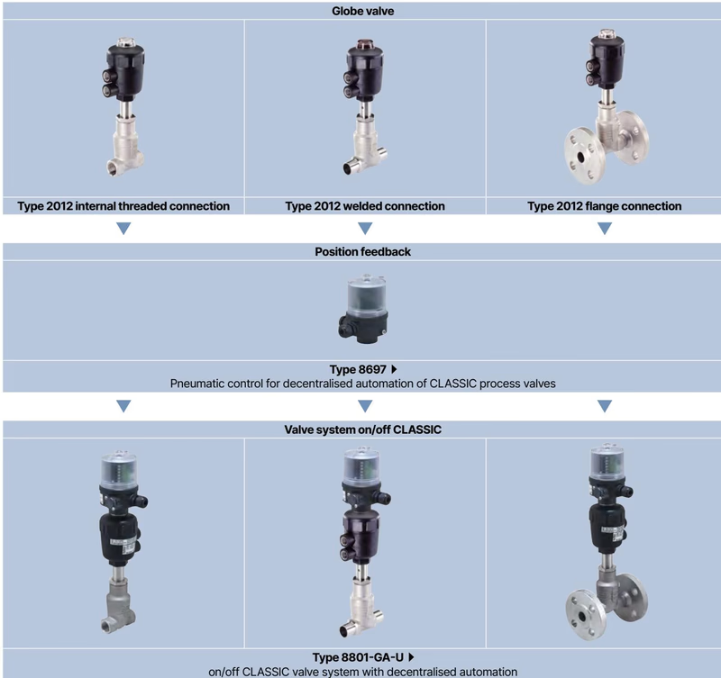
Type 2012 valves integrate directly with modular accessories to create automated packages:
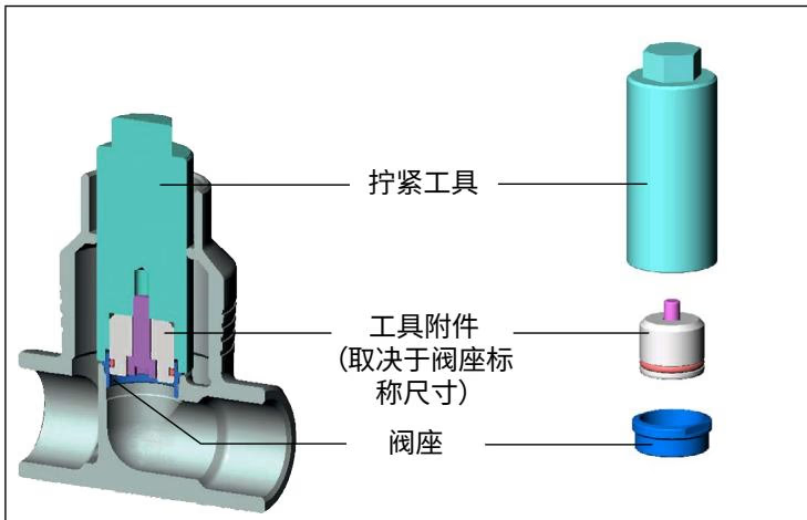
The actuator assembly is maintenance-free under normal operating conditions. Wetted wearing parts consist of the PTFE seat seal and the screwed-in valve seat ring.
| Fault Condition | Probable Cause | Corrective Action |
|---|---|---|
| Actuator fails to stroke | Pilot air line connected to wrong port | Connect control pressure to lower port for CFA |
| Pilot air pressure below 4.8 bar | Increase pilot air pressure to between 4.8 and 6.0 bar | |
| Medium pressure exceeds 16 bar | Reduce process line pressure to rated specification | |
| Internal seat leakage | Particulate contamination on seat | Clean seat surfaces; install an upstream strainer |
| Worn or grooved PTFE seat seal | Replace the seat seal assembly | |
| Flow direction reversed (flow above seat) | Reorient body to ensure flow enters below seat | |
| External leakage at relief weep hole | Worn spindle packing gland V-rings | Replace the spindle packing gland kit or actuator assembly |
Explore similar products in our catalog



