


PN25

BURKERT 20067288 (Type 2100) is a pneumatically operated 2/2-way DN20 G 3/4 angle seat valve with stainless steel CF3M body, PTFE seat seal, and flow-above-seat design for gases and vapours up to 16 bar.
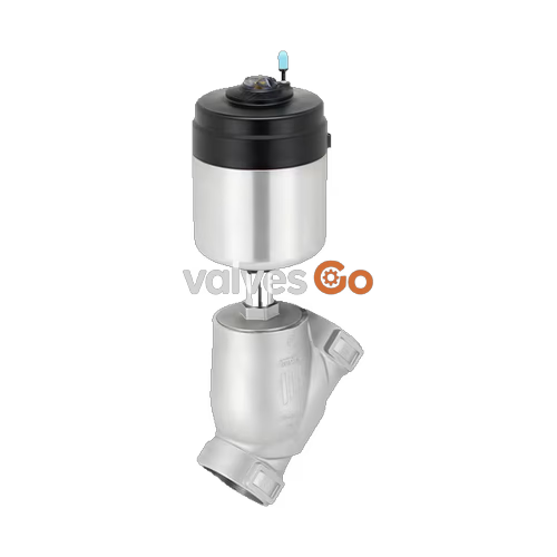
BURKERT 20067288 (Type 2100) is a pneumatically operated 2/2-way angle seat valve belonging to the ELEMENT series, engineered for decentralized process automation in industrial gas and vapour applications. Featuring a DN20 nominal diameter, G 3/4 female threaded ports, and an installation length of 75 mm, the valve combines a CF3M cast stainless steel body with a polyphenylene sulphide (PPS) actuator and stainless steel connection components.
The self-adjusting PTFE V-ring packing gland with spring compensation ensures stem seal integrity over extended operating cycles. Operating with control function A (normally closed by spring force), this valve variant is designed with media flow directed above the valve seat, allowing operating pressure up to 16 bar and delivering a water flow coefficient (Kv) of 11 m³/h. The device meets ingress protection ratings IP67 and NEMA 4X, and qualifies for CIP and SIP sanitization procedures.
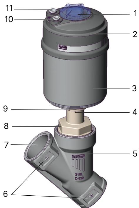
In control function A (CFA), internal spring tension acts through the spindle directly on the stainless steel swivel plate to maintain the valve in a normally closed state without pilot pressure. Applying compressed air to pilot air port 1 lifts the piston and spindle against the spring mechanism, opening the flow path.
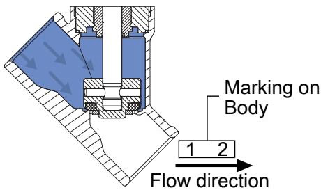
Model 20067288 is configured specifically for medium flow above the seat. In this arrangement, line pressure acts on the top of the swivel plate, contributing to the sealing force when the valve is closed.
Restricted Media for Flow Above Seat
Valves with flow direction above the seat must be used exclusively for gaseous media and vapours. Do not use this valve configuration for liquid media, because rapid closing against liquid flow causes severe pressure surges (water hammer) that can burst pipelines and destroy the valve body.
Operational limits vary according to medium temperature, pilot pressure, and applicable piping standards.
| Parameter | Value |
|---|---|
| Orifice / Nominal Size | DN20 (20 mm) |
| Fluidic Connection | G 3/4 female thread |
| Installation Length | 75 mm |
| Flow Direction | Above seat |
| Control Function | A (normally closed) |
| Operating Pressure Range | 0 to 16 bar |
| Pilot Pressure Range | 2.7 to 10 bar |
| Kv Value (Water) | 11 m³/h |
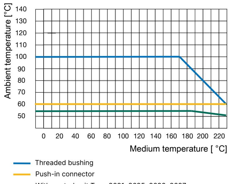
| Ambient Temperature (Push-in connector) | -10 °C to +60 °C |
| Ambient Temperature (Threaded bushing) | -10 °C to +100 °C |
| Medium Temperature (PTFE seal) | -10 °C to +200 °C |
| Storage Temperature | -20 °C to +65 °C |
| Protection Class | IP67 (EN 60529 / IEC 60529), NEMA 4X |
| Sound Pressure Level | < 70 dB(A) |
Maximum allowable operating pressure decreases at elevated medium temperatures. The table below details derating values across standards:
| Temperature [°C] | DIN EN 12516-1 / PN25 [bar] | ASME B16.34 Cl. 150 [bar] | JIS B 2220 10K [bar] |
|---|---|---|---|
| -10 to +38 / +50 | 25.0 | 19.0 | 14.0 |
| 100 | 24.5 | 16.2 | 14.0 |
| 150 | 22.4 | 14.8 | 13.4 |
| 200 | 20.3 | 13.7 | 12.4 |
| 230 | 19.0 | 12.7 | 11.7 |
Prior to mounting in the pipeline, ensure pipe sections are precisely aligned and free of weld spatter, burrs, and foreign particulate. Installations complying with DIN EN 161 (automatic shut-off valves for gas burners) require a strainer upstream that prevents the passage of a 1 mm mandrel.
When removing or reinstalling the actuator housing on the valve body, the valve must be held in the open position to protect the PTFE seat seal and internal drive spindle from torsional stress.
Pneumatic Actuation Required Before Disassembly
For valves with control function A, pressurise pilot air port 1 with compressed air at 5 bar to open the valve before unscrewing the body connection. Failure to open the valve before loosening can damage internal sealing components.
When reassembling, inspect the body seal for damage and lubricate the thread of the body connection (using Klüber paste UH1 96-402 or an equivalent medium-compatible lubricant). Apply 5 bar pilot air to port 1, thread the actuator assembly into the body, and tighten according to the specified torque:
| Nominal Diameter | Actuator Size | Tightening Torque [Nm] | Tolerance [Nm] |
|---|---|---|---|
| DN15 | 40 (C), 50 (D), 63 (E) | 45 | +10 / -5 |
| DN20 | 40 (C), 50 (D), 63 (E), 80 (F) | 50 | +10 / -5 |
| DN25 | 50 (D), 63 (E), 80 (F) | 60 | +10 / -5 |
| DN32 | 63 (E), 80 (F), 100 (G) | 65 | +10 / -5 |
| DN40 | 63 (E), 80 (F), 100 (G), 125 (H) | 65 | +10 / -5 |
| DN50 | 63 (E), 70 (M), 80 (F), 90 (N), 100 (G), 125 (H) | 70 | +10 / -5 |
The actuator housing can be rotated 360° to align pilot air ports with plant pneumatic lines.
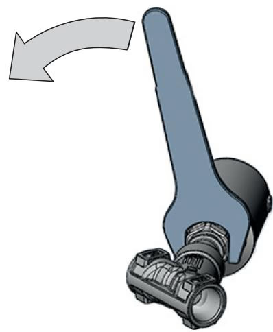
Rotational Alignment Procedure
Pneumatic pilot air must be supplied via neutral gases or clean compressed air using 6 mm external diameter hoses connected to the push-in fittings.
Routine inspection requires monitoring three primary functional locations for external or internal leakage.
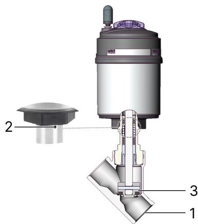
| Inspection Point | Observed Condition | Corrective Action |
|---|---|---|
| Media connectors (1) | Medium leaking at pipe joints | Re-tighten threaded joints or replace piping seals |
| Relief bore (2) | Medium or air escaping through relief hole | Replace spindle packing gland or replace complete actuator |
| Swivel plate / seat (3) | Internal seat leakage in closed position | Replace valve seat set (swivel plate) and inspect for debris |
| Problem | Possible Cause | Corrective Action |
|---|---|---|
| Actuator does not switch | Pilot air connected to wrong port | Connect control pressure supply to pilot air port 1 |
| Pilot pressure insufficient | Increase pilot pressure according to type label specifications | |
| Operating pressure exceeds limit | Reduce operating pressure below maximum rating (16 bar) | |
| Flow direction reversed | Align pipe flow with direction marked on valve body | |
| Valve seat is not tight | Particulates lodged between seat and seal | Flush pipeline or install an upstream strainer |
| PTFE swivel plate worn | Replace swivel plate assembly | |
| Leakage at relief bore | Spindle packing gland damaged or worn | Replace packing gland using dedicated socket tool |
Replacement of the internal spindle packing gland requires the dedicated socket wrench:
| Spindle ∅ [mm] | Nominal Diameter DN | Width Across Flats [mm] | Article Number |
|---|---|---|---|
| 10 | 15 to 50 | 19 | 683221 |
| 14 | 32 to 80 | 21 | 683223 |
Explore similar products in our catalog



