


PN25

BURKERT 20077819 (Type 2100) is a pneumatically operated 2/2-way NC angle seat valve with DN20 PN25 flange, stainless steel body, PTFE seat, 10 m³/h flow rate, and 0-16 bar operating pressure.
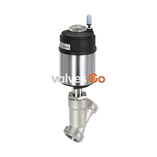
BURKERT 20077819 (Type 2100) is a pneumatically operated 2/2-way angle seat valve from the ELEMENT series, specifically engineered for decentralized process automation in demanding fluid handling environments. This configuration features a DN 20 nominal diameter with DIN EN 1092-1 PN 25 flanged connections and a face-to-face installation length of 220 mm. The valve operates under Control Function A (normally closed by internal spring force), introducing media flow below the valve seat to eliminate hydraulic water hammer in liquid processes while providing tight shut-off up to 16 bar operating pressure.
Constructed with an investment-cast stainless steel CF3M valve body and a resilient PTFE seat seal, Burkert 20077819 delivers a water flow coefficient (Kv) of 10 m³/h. Actuation is driven by a compact 50 mm (size D) pneumatic piston actuator constructed with a polyphenylene sulphide (PPS) cover and a 1.4561 (316Ti) stainless steel casing. The spindle gland utilizes self-adjusting PTFE V-rings with spring compensation to maintain stem sealing integrity across thermal cycles from -10 °C to +185 °C. All wetted materials meet Regulation (EC) 1935/2004 for food contact, and the entire assembly supports CIP/SIP cleaning processes.

Burkert Type 2100 utilizes a linear pneumatic piston actuator to drive a stainless steel spindle connected to an articulated swivel plate. In Control Function A (normally closed, NC), internal mechanical springs apply continuous downward closing force on the swivel plate against the valve seat. Introducing pilot air pressure of at least 5.2 bar into pilot air port 1 moves the actuator piston upward against the springs, lifting the plug clear of the flow passage.
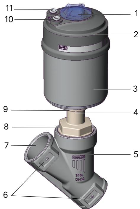
Flow enters beneath the seat (flow direction below the seat). Because process media pressure acts against the bottom of the swivel plate, inlet line pressure assists valve opening and prevents rapid plug impact against the seating surface upon closing.
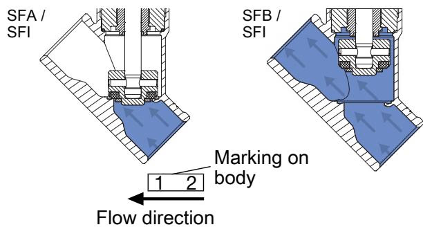
Liquid Media Operating Restriction
Valves installed with flow direction above the seat generate severe water hammer when closing against incompressible liquids, which can burst piping or shatter equipment. Liquid applications must strictly use flow direction below the seat as configured on article 20077819.
| Parameter | Specification |
|---|---|
| Article Number | 20077819 |
| Valve Type | Type 2100 ELEMENT |
| Configuration | Complete valve assembly, single-acting |
| Control Function | CFA: Normally closed by spring force |
| Flow Direction | Below seat (closes against flow) |
| Port Connection | Flange DIN EN 1092-1, PN 25 |
| Nominal Diameter (DN) | DN 20 (Seat size 20 mm) |
| Installation Length | 220 mm |
| Flow Coefficient Kv (water) | 10 m³/h |
| Operating Pressure Range | 0 bar(g) to 16 bar(g) |
| Minimum Pilot Pressure | 5.2 bar(g) |
| Maximum Pilot Pressure | 10 bar(g) |
| Control Medium | Clean compressed air, neutral gases |
| Pilot Air Connection | Push-in connector for external Ø 6 mm or 1/4" tubing |
| Seat Leakage Class | Rate A according to DIN EN 12266-1 (test medium: air) |
| Max. Permissible Viscosity | 600 mm²/s |
| Enclosure Rating | IP65 / IP67 according to EN 60529, NEMA Type 4X |
| Permissible Medium Temperature | -10 °C to +185 °C |
| Permissible Ambient Temperature | -10 °C to +60 °C (push-in connector limit) |
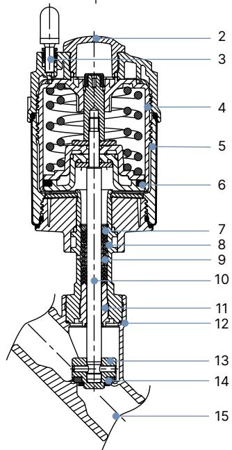
| Item No. | Component | Material |
|---|---|---|
| 1 | Ground terminal (optional ATEX) | Stainless steel 1.4301 / 1.4305 |
| 2 | Optical position indicator | Polysulfone (PSU) |
| 3 | Pilot air port | Polypropylene (PP) push-in fitting |
| 4 | Actuator cover | Polyphenylene sulphide (PPS) |
| 5 | Actuator casing | Stainless steel 1.4561 (316Ti) |
| 6 | Piston seal | Fluoroelastomer (FKM) |
| 7 | Spring assembly | Stainless steel 1.4310 |
| 8 | Spindle guide pipe | Stainless steel 1.4401 (316) / 1.4404 (316L) |
| 9 | Spindle packing gland | PTFE V-rings (carbon-filled), spring-compensated |
| 10 | Valve spindle | Stainless steel 1.4401 (316) / 1.4404 (316L) |
| 11 | Spindle guide bushing | PEEK |
| 12 | Body seal | Graphite (PTFE optional) |
| 13 | Swivel plate | Stainless steel 1.4401 (316) / 1.4404 (316L) |
| 14 | Valve seat seal | PTFE (Polytetrafluoroethylene) |
| 15 | Valve body | Investment cast stainless steel CF3M |
Food and Lubrication Compliance
All lubricants used in the packing gland and pneumatic actuator are certified according to NSF H1. Wetted non-metallic components comply with Regulation (EC) 1935/2004 pursuant to the manufacturer declaration.
Operating pressure limits are defined by the structural rating of the valve housing and the thermal resistance of seals according to DIN EN 12516-1 (PN 25 rating):
| Medium Temperature [°C] | Maximum Permissible Pressure PN 25 [bar] |
|---|---|
| -10 to +50 | 25.0 (valve seat rating limits unit to 16.0 bar) |
| +100 | 24.5 (valve seat rating limits unit to 16.0 bar) |
| +150 | 22.4 (valve seat rating limits unit to 16.0 bar) |
| +185 | 20.8 (valve seat rating limits unit to 16.0 bar) |
| +200 | 20.3 |
| +230 | 19.0 |
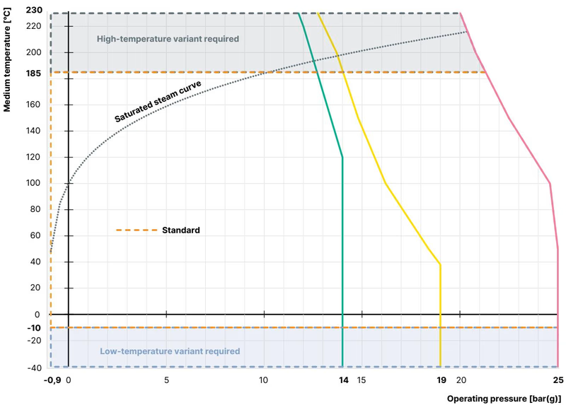
While the stainless steel body pressure boundary supports 25 bar, the internal spring mechanism and seat size on actuator 50 (D) establish a maximum operating shut-off rating of 16 bar across the seat.
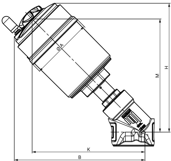
| Dimension Parameter | Size / Dimension (DN 20 / Actuator 50 D) |
|---|---|
| Actuator Size (Code) | 50 mm (D) |
| Actuator Outer Diameter (Ø A) | 64.5 mm |
| Height from Port Centerline to Top (B) | 174 mm |
| Total Height to Actuator Top (H) | 171 mm |
| Centerline to External Actuator Radius (K/M) | 155 mm |
| Face-to-Face Flange Length | 220 mm |
| Flange Standard | DIN EN 1092-1 Form B1, PN 25 |
Prior to mounting in the pipeline, lines must be thoroughly flushed of weld slag, scale, and foreign matter. Install the valve matching the body cast arrow to line flow. Position the actuator upright whenever possible.
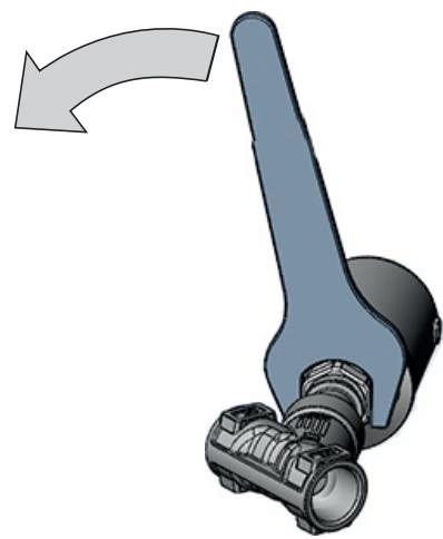
The actuator housing can be rotated continuously through 360° to optimize pneumatic supply routing:
When reinstalling an actuator onto the valve body, tighten the body joint to the exact specified torque:
| Nominal Diameter | Actuator Size | Tightening Torque [Nm] | Tolerance [Nm] |
|---|---|---|---|
| DN 15 | 50 (D) | 45 | +10 / -5 |
| DN 20 | 50 (D) | 50 | +10 / -5 |
| DN 25 | 50 (D) | 60 | +10 / -5 |
| DN 32 | 70 (M) | 65 | +10 / -5 |
| DN 40 | 70 (M) | 65 | +10 / -5 |
| DN 50 | 90 (N) | 70 | +10 / -5 |
Spring Hazard
The actuator cylinder contains pre-stressed internal springs under high tension. Do not attempt to unbolt or open the actuator casing.
Connect clean, dry pilot air (5.2 bar to 10 bar) to pilot air port 1 using 6 mm or 1/4" flexible tubing. Pilot air port 2 acts as a spring chamber exhaust vent and comes equipped with a loosely supplied silencer. In aggressive or corrosive washdown environments, connect a pneumatic hose to port 2 to pipe the spring chamber exhaust to a neutral atmosphere.
Commissioning must follow a controlled sequence:
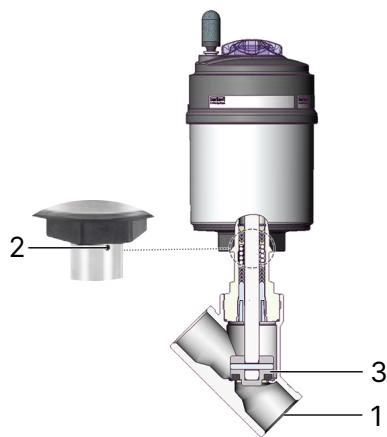
Inspect the valve periodically at three distinct inspection locations:
| Fault Condition | Probable Cause | Corrective Action |
|---|---|---|
| Actuator fails to stroke | Pilot pressure below 5.2 bar | Increase pilot air pressure to rated operating window (5.2 - 10 bar) |
| Pilot air connected to wrong port | Connect pilot supply line strictly to port 1 for CFA | |
| Line pressure exceeds 16 bar | Regulate process fluid operating pressure within specification | |
| Internal seat leakage | Debris trapped between plug and seat | Flush pipeline; install an upstream strainer with mesh retaining > 1 mm particles |
| PTFE seat seal worn or eroded | Replace swivel plate assembly using factory replacement kit | |
| External leakage at relief bore | Spindle V-ring packing worn | Replace spindle packing gland using installation tool 683221 (AF 19 mm socket) |
Burkert 20077819 can be directly integrated with ELEMENT series decentralized automation heads to create the Type 8801-YE automated valve system:
Explore similar products in our catalog



