


PN25

BURKERT 20082562 (Type 2961) is a manually operated 2-way globe control valve with DN 10 welded ends, equal percentage parabolic cone, PTFE seat seal, and nominal pressure rating PN25 (0-25 bar).
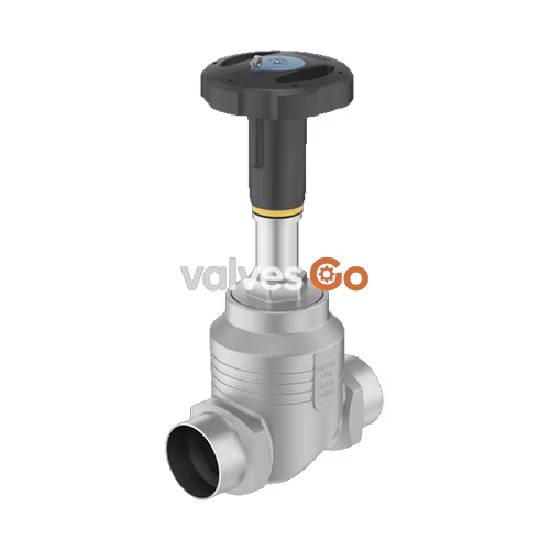
BURKERT 20082562 (Type 2961) is a manually operated 2-way globe control valve engineered for precise continuous flow control of liquids, steam, and neutral gases under demanding process conditions. Configured under article number 20082562, this assembly integrates a PPS manual actuator with an optical stroke scale and a 316L/CF3M stainless steel globe body featuring DN 10 (NPS 3/8) welded ends according to DIN EN ISO 1127, ISO 4200, and DIN 11866 Series B (pipe dimensions 17.2 x 1.6 mm). The valve is fitted with an exchangeable 6 mm stainless steel seat and an equal percentage parabolic control cone providing a theoretical rangeability of 50:1, rated for a nominal flow coefficient Kvs of 1.25 m³/h (Cv 1.5 gpm) and leakage class VI per DIN EN 60534-4 via a soft PTFE seat seal.
Type 2961 features a spindle guide made of PTFE-filled 316L stainless steel and a self-adjusting packing gland with filled PTFE V-rings and spring compensation, eliminating the need for manual gland retightening. The valve closes against the medium flow (flow below seat) and operates across an operating pressure range of 0 to 25 bar(g) with a medium temperature capability of -10 °C to +130 °C for the PTFE seat variant.
| Parameter | Technical Specification (Article 20082562) |
|---|---|
| Valve Type | Type 2961 2-way globe control valve |
| Article Number | 20082562 |
| Port Nominal Size | DN 10 (NPS 3/8) |
| Port Connection Type | Welded ends |
| Connection Standard | DIN EN ISO 1127 / ISO 4200 / DIN 11866 Series B |
| Pipe Outer Diameter x Wall Thickness | 17.2 x 1.6 mm |
| Valve Body Material | Stainless steel 316L / CF3M |
| Actuator Material | Polyphenylene sulphide (PPS) |
| Seat Diameter | 6 mm (1/4") |
| Seat Seal Material | PTFE (Polytetrafluoroethylene) |
| Flow Direction | Below seat (flow to open) |
| Flow Characteristic | Equal percentage parabolic cone (50:1) |
| Rated Flow Coefficient Kvs | 1.25 m³/h (Cv = 1.5 gpm) |
| Seat Leakage Class | Class VI according to DIN EN 60534-4:2006 |
| Nominal Pressure Class | PN 25 (DIN EN 1333), Class 150 (DIN EN 1759) |
| Operating Pressure Range | 0 to 25 bar(g) |
| Medium Temperature Range | -10 °C to +130 °C |
| Ambient Temperature Range | -10 °C to +60 °C |
| Maximum Medium Viscosity | 600 mm²/s |
| Handwheel Size / Diameter | Size S / 45 mm |
| Handwheel Travel Pitch | 1.25 mm per revolution |
| Actuator Interface | Spindle D10 |
| Body Screwing Tightening Torque | 45 Nm (±3 Nm) |
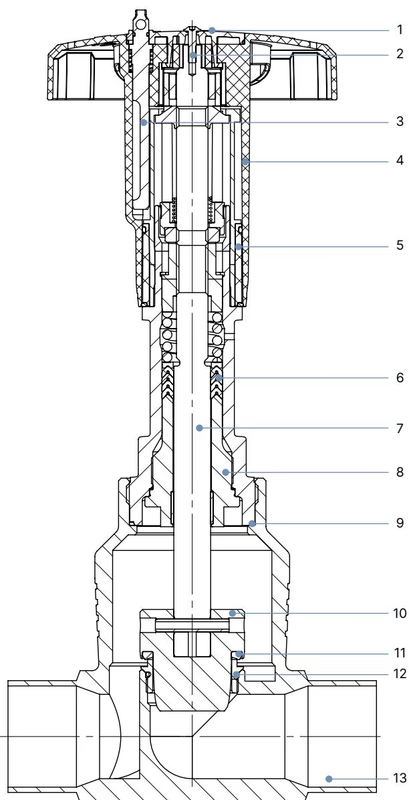
The mechanical construction of Type 2961 uses materials selected for chemical resistance and mechanical stability under high pressure and thermal cycling:
| Item No. | Element | Material |
|---|---|---|
| 1 | Cover | Polyamide (PA) |
| 2 | Screw | Stainless steel 1.4301 |
| 3 | Locking device | Stainless steel 1.4305 |
| 4 | Handwheel | Polyphenylene sulphide (PPS) |
| 5 | Visual position indicator with scale | Polyamide (PA) |
| 6 | Packing gland | PTFE V-rings (filled), with spring compensation |
| 7 | Stem | Stainless steel 1.4401 or 1.4404 |
| 8 | Spindle guide | Stainless steel 1.4404 (316L), PTFE filled |
| 9 | Housing seal | Graphite |
| 10 | Control cone | Stainless steel 1.4571 (optionally hardened) |
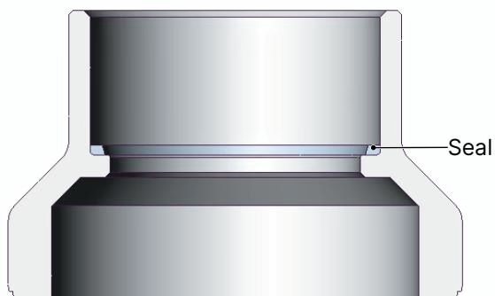
| 11 | Seat seal | PTFE (or optional PEEK) |
| 12 | Valve seat with O-ring | Stainless steel 1.4571, EPDM |
| 13 | Valve body | Stainless steel 316L / CF3M |
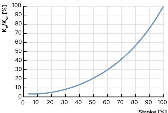
Type 2961 control valves conform to DIN EN 60534-2-4 flow characteristics. The parabolic plug geometry generates an equal percentage characteristic with a theoretical rangeability (Kvs/Kv0) of 50:1. For seat diameters up to 10 mm, the KvR value is defined at 10% of stroke, representing the smallest Kv value at which the tilt tolerance according to DIN EN 60534-2-4 is maintained.
For article 20082562 with DN 10 port connection and 6 mm seat orifice, flow rates measured with water per DIN EN 60534-2-4 across opening stroke increments are structured as follows:
| Stroke (%) | Kv Value [m³/h] | Rangeability | Max Operating Pressure [bar(g)] | Seat Leakage Class |
|---|---|---|---|---|
| 5% | 0.005 | 50:1 | 25 | Class VI (PTFE) |
| 10% | 0.007 | 50:1 | 25 | Class VI (PTFE) |
| 20% | 0.011 | 50:1 | 25 | Class VI (PTFE) |
| 30% | 0.045 | 50:1 | 25 | Class VI (PTFE) |
| 40% | 0.085 | 50:1 | 25 | Class VI (PTFE) |
| 50% | 0.16 | 50:1 | 25 | Class VI (PTFE) |
| 60% | 0.26 | 50:1 | 25 | Class VI (PTFE) |
| 70% | 0.41 | 50:1 | 25 | Class VI (PTFE) |
| 80% | 0.65 | 50:1 | 25 | Class VI (PTFE) |
| 90% | 1.10 | 50:1 | 25 | Class VI (PTFE) |
| 100% | 1.25 | 50:1 | 25 | Class VI (PTFE) |
| Kvs | 1.25 | 50:1 | 25 | Class VI (PTFE) |
| Tight Sealing Required | Leakage Class (DIN EN 60534-4) | Medium Temperature Range | Seat Seal Material |
|---|---|---|---|
| No (Additional shut-off valve recommended) | Class II (0.5% nominal flow permissible) | -40 °C to +230 °C | Stainless steel (metallic seal) |
| Yes (Tight shut-off achieved) | Class VI (soft seal) | -40 °C to +130 °C (recommended for ≤ +130 °C) | PTFE (Fitted in 20082562) |
| Yes (Tight shut-off achieved) | Class VI (soft seal) | -10 °C to +230 °C (recommended for > +130 °C) | PEEK |
Flow Direction and Seating
The valve must be installed with flow entering beneath the seat (flow to open). Closing the valve moves the parabolic plug downward against the oncoming medium flow, ensuring stable positioning without flutter.
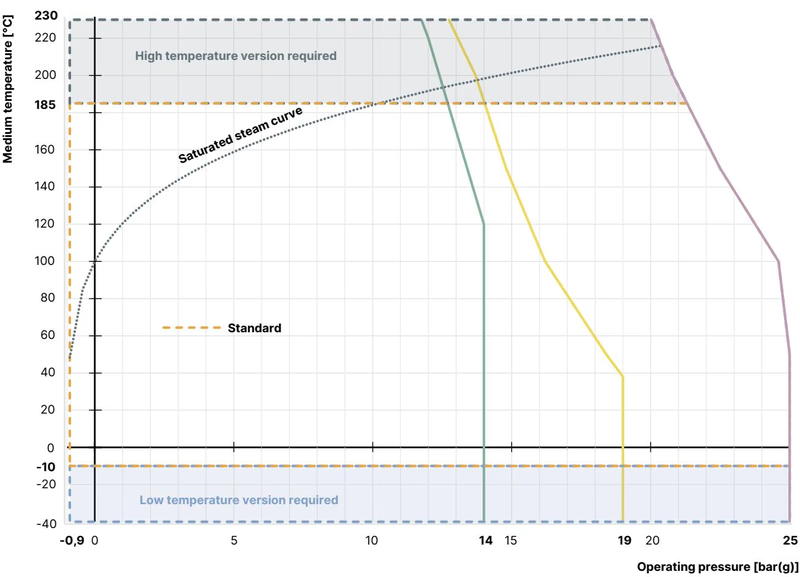
Maximum allowable working pressures are governed by temperature derating curves in accordance with DIN EN 12516-1 (PN25), ASME B16.34 (Class 150), and JIS B 2220 (10K).
| Temperature [°C] | Maximum Permissible Operating Pressure [bar] |
|---|---|
| -10 to +50 | 25.0 |
| +100 | 24.5 |
| +150 | 22.4 |
| +200 | 20.3 |
| +230 | 19.0 |
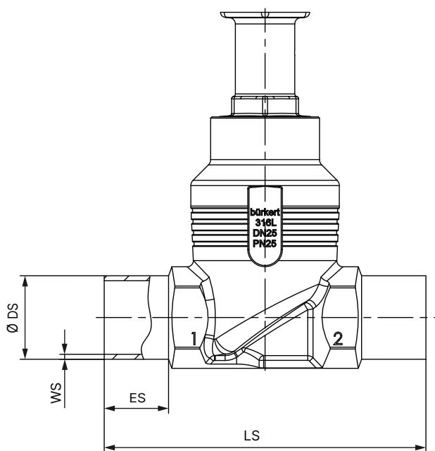
| Nominal Diameter DN | External Pipe Diameter (∅ DS) [mm] | Wall Thickness (WS) [mm] | Body Face-to-Face Length (LS) [mm] | Weld End Extension (ES) [mm] |
|---|---|---|---|---|
| 10 (Article 20082562) | 17.2 | 1.6 | 90 | 20 |
| 15 | 21.3 | 1.6 | 90 | 20 |
| 20 | 26.9 | 1.6 | 100 | 20 |
| 25 | 33.7 | 2.0 | 130 | 26 |
| Handwheel Size | Handwheel Diameter ∅ [mm] | Height H1 [mm] | Height H2 (with Lock) [mm] | Slope per Revolution [mm] | Applicable Pipe Sizes |
|---|---|---|---|---|---|
| S (Small) | 45 | 217 | 224 | 1.25 | DN 10 to DN 25 |
| M (Medium) | 110 | 296 to 307 | 303 to 313 | 1.75 | DN 32 to DN 50 |
| L (Large) | 160 | 361 to 379 | 368 to 385 | 2.00 | DN 65 to DN 100 |
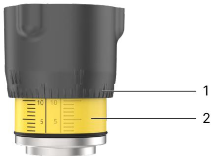
Turning the handwheel counterclockwise lifts the spindle and opens the valve port, while clockwise rotation closes it. The manual actuator integrates two visual indication elements:
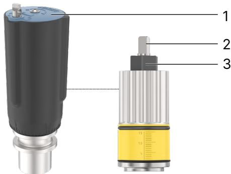
Both minimum and maximum valve openings can be mechanically bounded via the internal adjustment sleeve:
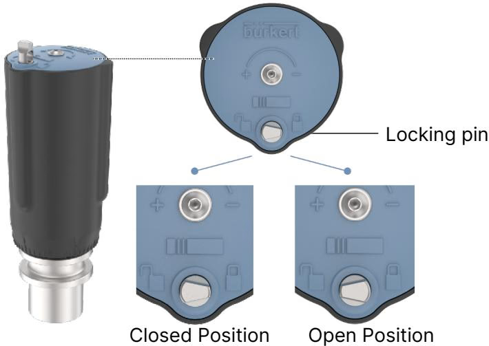
The handwheel locking device secures the valve against accidental or unauthorized operation:
Tight Sealing under Interlock
Leakage class VI tightness cannot be guaranteed when the valve is locked in the closed position using the interlock pin, due to variations in thermal expansion and operational seated pressure.
Welded Body Installation
For valves with welded ends, the actuator must be disassembled from the body before welding into the pipeline to prevent thermal damage to internal PTFE components and actuator plastics.
Under normal operation according to manual specifications, the PPS actuator is maintenance-free. Annual visual inspection is recommended, including checking the actuator relief bore for fluid discharge indicative of packing gland wear.
| Fault | Possible Cause | Corrective Action |
|---|---|---|
| Valve does not seal tightly | Particulate entrapment between seat and plug | Install upstream strainer or dirt trap |
| Valve seat seal worn or damaged | Replace seat / closure member | |
| Reverse flow orientation | Reorient valve so flow enters below seat | |
| Operating pressure exceeds limit | Verify line pressure against type label limits | |
| Fluid escaping through relief bore | Packing gland V-rings worn | Replace packing gland seal kit |
Type 2961 conforms to the European Pressure Equipment Directive 2014/68/EU. Wetted materials are available with FDA compliance (Code of Federal Regulations, variable codes PL02/PL03), USP Class VI biocompatibility (variable code PL04), Regulation (EC) No 1935/2004 (codes PL01/PL02), and China food GB standards (variable code PL10).
When ordered with variable code PX51, Type 2961 valves comply with ATEX and IECEx mechanical explosion protection directives:
Explore similar products in our catalog



