PN25

BURKERT 20086946 Type 3321 is an electromotive 2/2-way on/off globe valve with G 3" thread, AG3 10000 N actuator, PEEK seat seal, 0–17 bar operating pressure, and büS service interface.
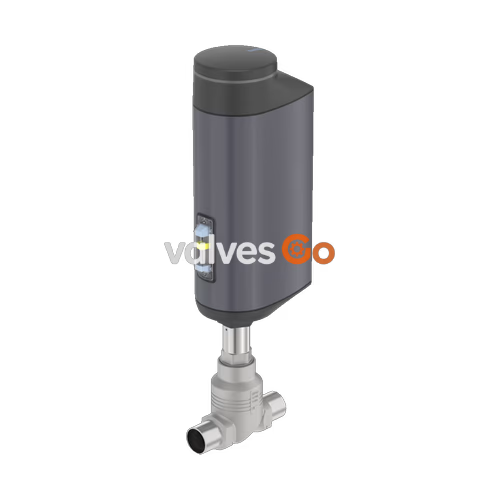
BURKERT 20086946 (Type 3321) is an electromotive 2/2-way globe shut-off valve designed for demanding process isolation under demanding industrial conditions. Configured with a G 3" internal threaded connection (DN 80 seat size) and an AG3 linear electromotive actuator delivering 10,000 N positioning force, this valve executes rapid flow isolation with a typical closing time of 8.7 seconds at 3 mm/s travel speed. Flow travels below the valve seat (port direction 2 → 1), providing a flow coefficient $K_v$ of 110 m³/h ($C_v$ 127.2 gpm). The wetted construction pairs a cast stainless steel CF3M valve body with a 1.4571 stainless steel seat, 1.4571 swivel plate, PEEK seal washer, and spring-compensated PTFE V-ring spindle packing. Operating pressure spans 0 to 17 bar(g) with medium temperatures from -10 °C to +185 °C. The wetted assembly meets EC Regulation 1935/2004 for food contact.
| Parameter | Specification |
|---|---|
| Valve Type | 2/2-way electromotive globe on/off valve |
| Order Code / Article Number | 20086946 |
| Type Series | 3321 |
| Nominal Diameter / Seat Size | DN 80 (3"), 80 mm seat diameter |
| Process Connection | G 3" internal thread (DIN ISO 228-1) |
| Flow Direction | Below seat (direction 2 → 1) |
| Flow Rate Water ($K_v$) | 110 m³/h (DIN EN 60534-2-4) |
| Flow Rate Water ($C_v$) | 127.2 gpm |
| Operating Pressure Range | 0...17 bar(g) |
| Nominal Pressure | PN 25 (DIN EN 1333), Class 150 (DIN EN 1759) |
| Seat Leakage | Leakage rate A (DIN EN 12266-1, test medium air) |
| Medium Temperature | -10 °C...+185 °C |
| Ambient Temperature | -25 °C...+65 °C (without additional fieldbus module) |
| Actuator Size / Driving Force | AG3 (10,000 N linear force) |
| Typical Closing Time | 8.7 s |
| Travel Speed | 3 mm/s |
| Supply Voltage | 24 V DC ± 10 % (maximum ripple 10 %) |
| Operating Current | Max. 5 A at maximum load (additionally 6 A at minimum operating temperature) |
| Standby Power Consumption | 2...4 W |
| Duty Cycle | 100 % continuous |
| Electrical Protection Class | Class III (DIN EN 61140) |
| Ingress Protection | IP65 / IP67 (DIN EN 60529), NEMA 4X |
| Control Mode | Binary (0...5 V = log '0', 10...30 V = log '1') |
| Digital Inputs / Outputs | 1 digital input, 2 digital outputs (current limit 100 mA) |
| Service Interface | büS service interface (micro-USB connection) |
| User Interface | Blind cover with internal push buttons and 4 DIP switches (no display) |
| Power Loss Reaction | Blocked in last static position (no energy storage module installed) |
| Medium Viscosity | Up to 600 mm²/s |
| Food Conformity | EC Regulation 1935/2004 compliant (manufacturer declaration) |
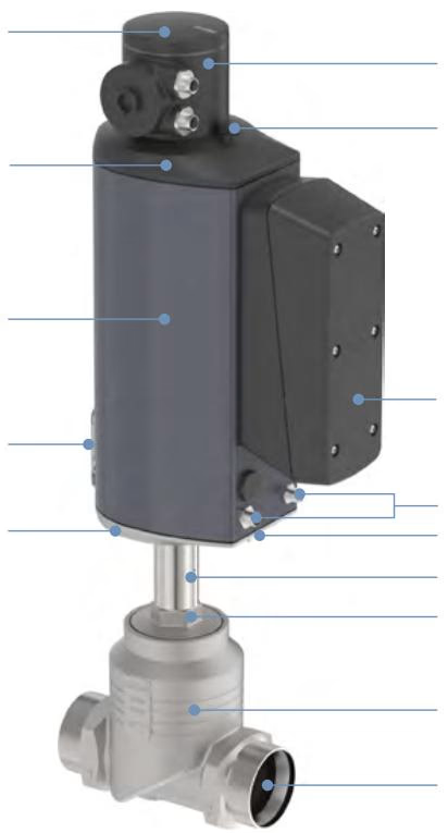
Actuator housing components and process-wetted valve internals are manufactured from high-grade metals and engineering polymers engineered for chemical resistance and external washdown.
| Item | Component | Material |
|---|---|---|
| 1 | Blind cover / gateway housing | PPS (standard), stainless steel 1.4301 (ATEX/IECEx optional) |
| 2 | Actuator cover | Polycarbonate (PC) |
| 3 | Seal | EPDM |
| 4 | Actuator housing | Powder-coated aluminium |
| 5 | Energy storage housing (when fitted) | Polycarbonate (PC) |
| 6 | Seal | EPDM |
| 7 | Actuator base | Stainless steel 1.4308 |
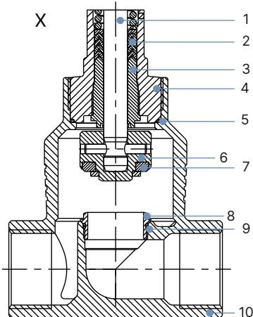
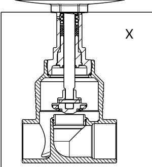
| Item | Component | Material |
|---|---|---|
| 1 | Spindle | Stainless steel 1.4401 (316) / 1.4404 (316L) |
| 2 | Spindle seal | PTFE V-seals (filled) with spring compensation |
| 3 | Spindle guide | PEEK or stainless steel 1.4404 (316L) |
| 4 | Packing gland tube | Stainless steel 1.4401 (316) |
| 5 | Valve body seal | Graphite or PTFE |
| 6 | Swivel plate | Stainless steel 1.4571 |
| 7 | Valve seat seal | PEEK seal washer (PTFE optional in lower temp ranges) |
| 8 | Valve seat | Stainless steel 1.4571 |
| 9 | O-ring valve seat | EPDM or PTFE |
| 10 | Valve body | Stainless steel CF3M |
Chemical Resistance Assessment
Material compatibility for aggressive process fluids can be validated through the Bürkert resistApp chemical resistance chart available on the manufacturer website.
Actuator height and body face-to-face dimensions govern mechanical pipe layout. For actuator size AG3 mounted on a DN 80 port connection, the standard total height H1 (without optional fieldbus gateway module) is 628 mm. When an optional fieldbus gateway is mounted, total height H2 increases to 700 mm. In the closed position without sealing load, the actuator is raised by approximately 2 mm.
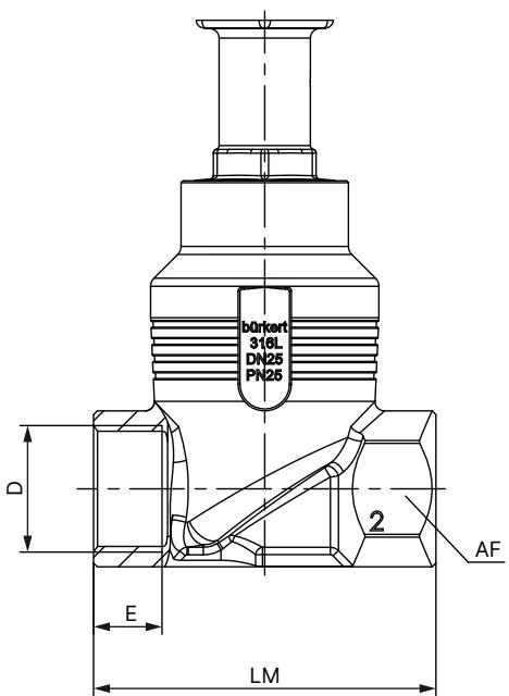
| DN | NPS | G Thread Depth E [mm] | NPT Depth E [mm] | RC Depth E [mm] | Body Length LM [mm] | Wrench Flat AF [mm] |
|---|---|---|---|---|---|---|
| 10 | 3/8 | 12 | 10.3 | 10.1 | 65 | 27 |
| 15 | 1/2 | 14 | 13.7 | 13.2 | 65 | 27 |
| 20 | 3/4 | 16 | 14 | 14.5 | 75 | 34 |
| 25 | 1 | 18 | 16.8 | 16.8 | 90 | 41 |
| 32 | 1 1/4 | 20 | 17.3 | 19.1 | 110 | 50 |
| 40 | 1 1/2 | 22 | 17.3 | 19.1 | 120 | 55 |
| 50 | 2 | 24 | 17.6 | 23.4 | 150 | 70 |
| 65 | 2 1/2 | 26 | 23.7 | 26.7 | 185 | 85 |
| 80 | 3 | 28 | 30.5 | 29.8 | 205 | 100 |
| 100 | 4 | 32 | 33 | 35.8 | 240 | 125 |
For 20086946 with G 3" connection (DN 80), body face-to-face length LM is 205 mm, thread depth E is 28 mm, and width across wrench flats AF is 100 mm.
Electrical connection of the AG3 actuator variant is accomplished via round multipole M12 circular connectors located on the side of the actuator base alongside a separate functional earth terminal.
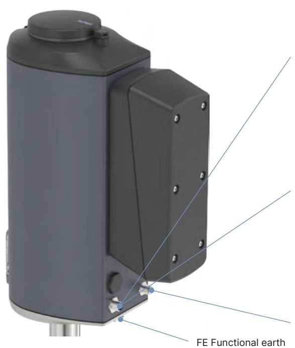
| Pin | Signal Assignment |
|---|---|
| 1 | Digital input + |
| 2 | GND for digital input and digital outputs |
| 3 | Digital output 2 + |
| 4 | Digital output 1 + |
| 5 | Do not connect |
| 6 | Do not connect |
| 7 | Do not connect |
| 8 | Do not connect |
| Pin | Power Assignment |
|---|---|
| 1 | Operating voltage 24 V DC ± 10 % |
| 2 | Do not connect |
| 3 | GND (power supply ground) |
| 4 | Do not connect |
| FE | Functional earth, connected directly to housing |
Maximum working pressure for DN 80 equipped with an AG3 10,000 N actuator and PEEK seat seal washer is rated to 17 bar(g) with fluid flow oriented below the seat. Permissible ambient temperature correlates directly with process medium temperature.
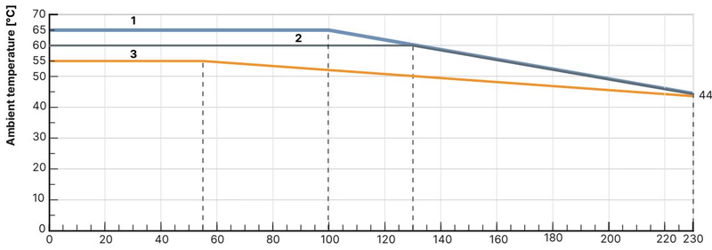
In the AG3 derating chart, Curve 1 represents devices without auxiliary modules (such as 20086946). At lower medium temperatures, ambient temperatures up to +65 °C are permissible. As medium temperatures approach +185 °C, derating applies according to standard convective dissipation boundaries.
Power Interruption Behavior
Article 20086946 is configured without the internal SAFEPOS energy storage module. Upon loss of the 24 V DC electrical supply, the linear spindle mechanically blocks in its instantaneous position under process pressure up to the rated 17 bar.
Linear movement is produced by a brushless DC motor linked to a ball screw drive system, applying direct thrust to the spindle. The closed exterior features detergent resistance verified against Ecolab test method F&E/P3-E No. 40-1. Position detection is continuously monitored through an internal non-contact sensor system.
Mechanical Override Torque Limit
When manually positioning the valve via the mechanical 4 mm hex drive, do not exceed the maximum tightening torque of 2 Nm at the travel end stops.
Wear components on the Type 3321 are field-replaceable using factory spare part sets. Servicing can be performed on the swivel plate, packing gland seals, spindle guide, and seat assembly.
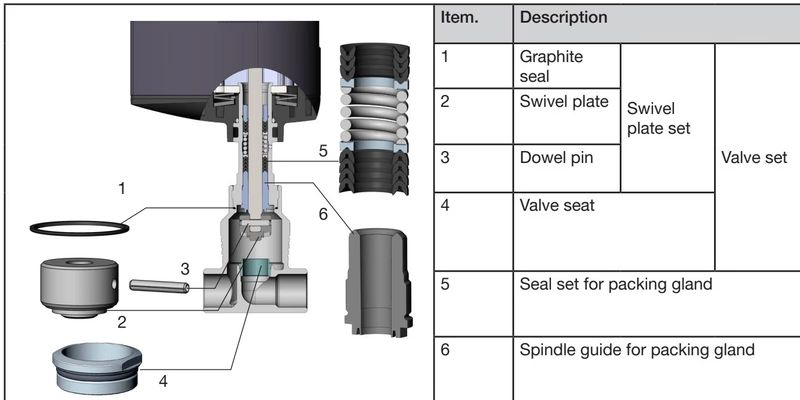
Pressure Hazard and Removal Precaution
Before unbolting the actuator or disassembling valve components, isolate system pressure and vent all piping lines completely. To avoid permanent seat seal damage, always drive the valve into the fully OPEN position before unscrewing the actuator from the valve body.
| Connection Size Valve Body DN [mm] | Body Tightening Torque [Nm] |
|---|---|
| 10, 15 | 45 ±3 |
| 20 | 50 ±3 |
| 25 | 60 ±3 |
| 32, 40 | 65 ±3 |
| 50 | 70 ±3 |
| 65 | 100 ±3 |
| 80 | 120 ±5 |
| 100 | 150 ±5 |
After reassembling the actuator to a replaced valve body or installing a new valve seat set, run the automated X.TUNE function to calibrate the physical stroke limits:
Explore similar products in our catalog