Transit-Time Ultrasonic

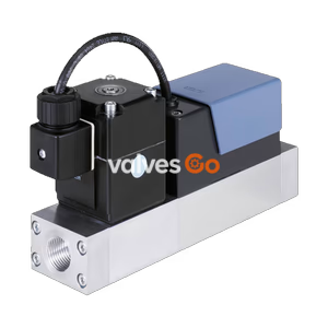
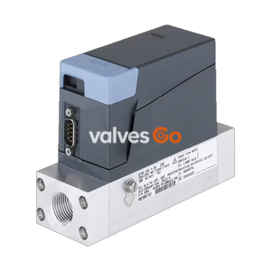
BURKERT 20090659 (Type 8745) is an inline thermal mass flow controller for CO2 with a 200 Nl/min nominal range, G 1/4 connection, Type 2875 electromagnetic valve, 4-20 mA interface, and IP20 aluminum body.
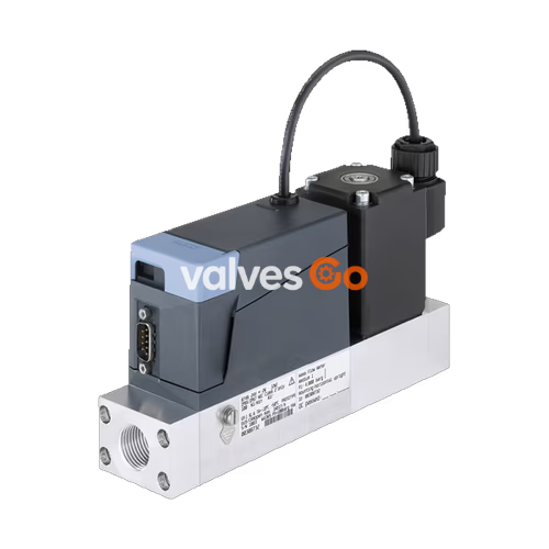
BURKERT 20090659 (Type 8745) is an inline thermal mass flow controller (MFC) configured for precise metering and control of carbon dioxide (CO2). Built with an aluminium base block and a direct-acting Type 2875 electromagnetic proportional valve, the device delivers a nominal flow rate of 200 Nl/min with a 1:50 control turndown. The instrument operates on 24 V DC power and communicates set-point and process feedback via standard 4...20 mA analog signals through a 9-pin D-Sub connector. The fluidic body integrates an internal G 1/4" process port, FKM seat and external sealing, and an onboard thermal sensor placed directly in the main gas stream to combine settling times below 500 ms with minimal pressure drop.
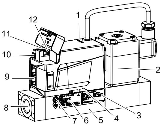
Article 20090659 represents a factory-calibrated Type 8745 execution defined by the following manufacturing properties:
| Technical Parameter | Source Specification |
|---|---|
| Product Type | 8745 Mass Flow Controller (MFC) |
| Article Number (SKU) | 20090659 |
| Operating Medium | Carbon dioxide (CO2) |
| Calibration Medium | Real gas calibration (CO2) |
| Nominal Flow Rate ($Q_N$) | 200.00 Nl/min (referenced to 1.013 bar abs, 0 °C) |
| Inlet Operating Pressure ($p_1$) | 2.5 bar (ü) |
| Outlet Pressure at $Q_{nom}$ ($p_2$) | 0 bar (ü) |
| Maximum Medium Pressure ($p_{max}$) | 3 bar (ü) |
| Actuator Type | Type 2875 electromagnetic proportional valve |
| Orifice Seat Diameter | 4.0 mm (5/32") |
| Base Block Material | Aluminium |
| Sealing Materials | FKM (valve seat seal and external seals) |
| Process Connection | G 1/4" female thread (DIN ISO 228/1) |
| Installation Position | Horizontal |
| Supply Voltage | 24 V DC (±10%, residual ripple < 2%) |
| Control Signals | 4...20 mA input, 4...20 mA output |
| Electrical Interface | 9-pin D-Sub DE-9 male plug |
| Ingress Protection | IP20 |
Type 8745 operates on the Constant Temperature Anemometer (CTA) principle. The thermal sensor features two temperature-dependent resistors positioned directly in the main medium stream alongside three passive resistors outside the flow channel, forming a balanced Wheatstone bridge.
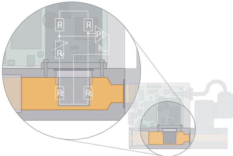
The first in-stream resistor measures the actual gas temperature, while the second low-resistance sensor element is heated to maintain a constant defined temperature difference above the fluid. The electrical heating current required to preserve this temperature differential corresponds directly to the heat dissipated by the flowing gas, serving as the primary measurement signal. Internal flow profiling elements within the fluidic channel and factory calibration ensure that mass flow rate is derived with high precision.
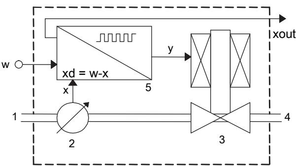
In closed-loop control operation, the integrated electronics continuously compare the measured mass flow rate ($x$) against the incoming set-point value ($w$). The controller computes the required valve position variable ($y$) to drive the direct-acting electromagnetic proportional valve (Type 2875). Because the valve is normally closed (NC) when de-energized, it provides a safe shut-off function under nominal pressure conditions.
| Feature | Value |
|---|---|
| Measuring Accuracy | $\pm 1.5%$ of measured value $\pm 0.3%$ of full scale (after < 1 min warm-up) |
| Repeatability | $\pm 0.1%$ of full scale |
| Control Span (Turndown) | 1:50 |
| Settling Time ($t_{95}$) | < 500 ms |
| Gas Temperature Range | -10 °C to +70 °C |
| Ambient Operating Temperature | -10 °C to +50 °C |
| Storage Temperature | -10 °C to +70 °C |
| Permissible Ambient Humidity | < 95% at +55 °C, non-condensing |
| Power Consumption | Max. 12.5 W to 31.5 W during MFC operation (dependent on proportional valve) |
| Analogue Input Impedance | < 300 Ω (for current input 4...20 mA) |
| Analogue Output Max. Load | 400 Ω (for current output 4...20 mA) |
| Status Display | RGB LED conforming to NAMUR NE107 |
BURKERT 20090659 uses a 9-pin D-Sub DE-9 male connector for power, analogue setpoint/actual signals, digital triggering, and relay monitoring.
| Pin | Signal Assignment | Functional Description |
|---|---|---|
| 1 | Digital input | Remote trigger (Autotune, gas selection, setpoint source) |
| 2 | GND | Common ground for power supply and digital input |
| 3 | +24 V DC | Operating voltage supply (24 V DC ±10%) |
| 4 | Relay NC | Potential-free relay normally closed contact (break contact) |
| 5 | Relay Reference | Potential-free relay reference contact |
| 6 | Set-point input + | Analogue set-point input (4...20 mA) |
| 7 | Set-point GND | Analogue set-point ground reference |
| 8 | Actual value output + | Analogue measured flow output (4...20 mA) |
| 9 | Actual value GND | Analogue output ground reference |
| Housing | Shield / FE | Functional earth connection via connector shell |
Relay and Digital Input Ratings
The digital input accepts 0...0.2 V for low level, 1...4 V (or open) for open level, and 5...28 V for high level. The onboard relay contacts are rated for a maximum of 1 A at 30 V DC / 30 VA. By default, the relay indicates when the flow setpoint cannot be reached.
Functional Earthing Requirement
Connect the functional earthing terminal on the aluminium body to prevent electrostatic build-up and guarantee compliance with EMC directives. Loosen the M4 grounding screw with a 6.5 mm flat screwdriver, insert an earthing cable lug (green/yellow, cross-section equal to or greater than the power supply conductors), and tighten to 1.8...2.0 N·m (1.33...1.47 lbf·ft).
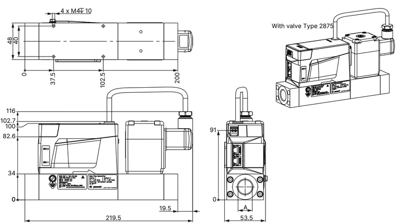
Article 20090659 utilizes base block size 00 / A1 suited for nominal flow rates up to 1500 Nl/min. The process connections consist of G 1/4" female parallel threads according to DIN ISO 228/1 with a thread engagement depth of 12 mm.
Installation guidelines:
Before initial operation, flush and vent the supply piping completely at the calibration pressure (2.5 bar ü). If local installation piping alters inlet pressure dynamics, execute the integrated Autotune routine to optimize closed-loop control parameters.
Commissioning with Bürkert Communicator
Connect a PC running the Bürkert Communicator software (Type 8920) to the micro-USB service büS interface using the USB-büS Interface Set 2 (article 772551). Activate the bus terminating switch on the büS stick before plugging into the PC. Never connect an external power source to the micro-USB port; power must be supplied exclusively through pins 2 and 3 of the D-Sub connector.
Type 8745 features an internal slot for a configuration memory card. All calibration curves, zero-point adjustments, and parameter sets are mirrored on this card. If hardware replacement is required, inserting the memory card into another unit of identical article number (20090659) automatically restores operating parameters.
Under clean gas conditions complying with ISO 8573-1 (Class 2 particles ≤ 1 µm, Class 4 dew point ≤ 3 °C, Class 1 oil ≤ 0.01 mg/m³), the device operates without routine servicing. If media carry particulate impurities, the integrated mesh filter located in the inlet port must be inspected periodically.
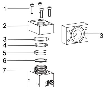
Filter disassembly procedure:
Explore similar products in our catalog