Transit-Time Ultrasonic

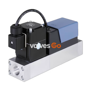
BURKERT 20092146 Type 8745 mass flow controller regulates N2 up to 350 Nl/min via an inline CTA thermal sensor and Type 2836 proportional valve, featuring 4-20 mA I/O and G 1/4 ports.
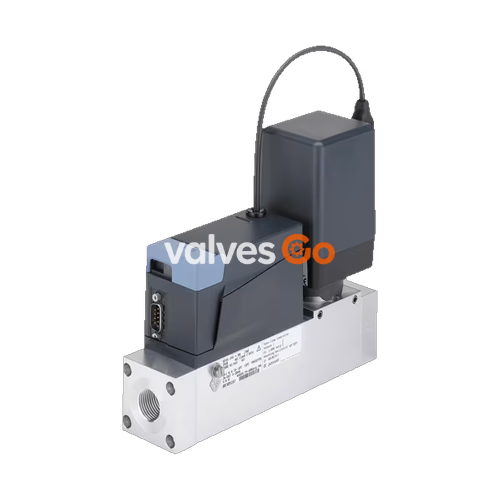
BURKERT 20092146 (Type 8745) is a thermal mass flow controller configured for high-flow gas regulation up to 350 Nl/min of nitrogen (N2). Operating on an inline Constant Temperature Anemometer (CTA) thermal sensor principle directly in the main stream, the instrument executes closed-loop flow control with minimal pressure loss. Actuation is delivered by an integrated Bürkert Type 2836 direct-acting electromagnetic proportional valve with a 5.0 mm seat orifice, ensuring dynamic response times under 500 ms.
Configured in an aluminium fluidic body with FKM seals, article 20092146 incorporates G 1/4" internal threaded process connections and a 9-pin D-Sub interface supporting 4–20 mA analogue setpoint and actual value signals, 1 digital input, and 1 relay output. Up to four calibration curves can be stored on the instrument, enabling flexibility across shifting process parameters.
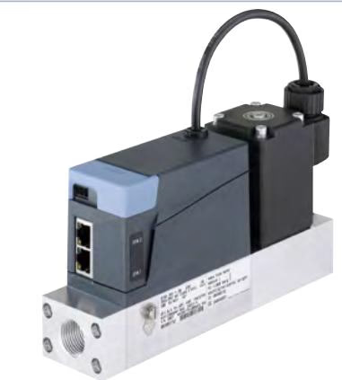
Article 20092146 defines a specific build of the modular Type 8745 platform, equipped with the following technical parameters:
| Parameter | Value |
|---|---|
| Article Number | 20092146 |
| Type Family | 8745 |
| Device Function | Controller (MFC) |
| Operating Medium 1 | N2 nitrogen |
| Calibration Medium 1 | Air |
| Nominal Operating Range | 350 Nl/min |
| Turndown Ratio | 1:50 |
| Normal Operating Pressure | 4 bar(ü) |
| Maximum Medium Pressure | 6 bar |
| Outlet Pressure at Qnom | 3 bar |
| Installation Position | Horizontal |
| Port Connection 1 | Internal thread G 1/4" (Standard G) |
| Actuator Model | Type 2836 direct-acting electromagnetic proportional valve |
| Valve Seat Diameter | 5 mm (3/16") |
| Fluidic Body Material | Aluminium |
| Valve Seat Seal | FKM (Fluor rubber) |
| External Seal Material | FKM (Fluor rubber) |
| Operating Voltage | 24 V DC |
| Electrical Connection | D-Sub 9-pin male |
| Analogue Setpoint Signal | 4–20 mA input |
| Analogue Feedback Signal | 4–20 mA output |
| Digital Quantity Inputs / Outputs | 1 digital input / 1 relay contact output |
| Protection Class | IP20 (with mating connector attached) |
Type 8745 operates either as a mass flow controller (MFC) or mass flow meter (MFM) for gases across nominal flow ranges from 20 Nl/min up to 2500 Nl/min (referenced to nitrogen at 1.013 bar abs and 0 °C).
| Technical Category | Specification Details |
|---|---|
| Housing Material | Polycarbonate (PC) |
| Base Block Materials | Aluminium or stainless steel 1.4404 / 316L |
| Sensor Wetted Materials | Stainless steel 1.4404 / 316L, Al2O3, PPS GF40, epoxy resin, silicon, silicon nitride |
| Supply Voltage | 24 V DC (±10% tolerance, residual ripple ±2%) |
| Operating Medium | Neutral, pure gases (others on request) |
| Calibration Media | Operating medium or air |
| Medium Temperature | -10 °C to +70 °C (-10 °C to +60 °C with oxygen; 0 °C min. for electromotive valve) |
| Ambient Temperature | -10 °C to +50 °C (higher temperatures on request) |
| Storage Temperature | -10 °C to +70 °C |
| Relative Humidity | Max. 95% at +55 °C, non-condensing |
| Degree of Protection | IP20 |
| Analogue Interfaces | 4–20 mA, 0–20 mA, 0–10 V, or 0–5 V (input impedance > 20 kΩ voltage, < 300 Ω current) |
| Digital Communications | Modbus RS-485 / RTU, Industrial Ethernet: EtherCAT®, EtherNet/IP, Modbus TCP, PROFINET |
| Process Port Connections | G or NPT 1/4", 3/8", 1/2", 3/4", 1", sub-base, clamp connection (DN 20 to DN 40) |
The Type 8745 series supports two distinct valve actuation technologies:
| Functional Characteristic | Electromagnetic Proportional Valve (Type 287x / 2836) | Electromotive Proportional Valve (Type 3280 / 3285) |
|---|---|---|
| Valve Position (De-energised) | Normally closed | Remains in current position (holds position) |
| Nominal Orifice Diameter | 0.8 mm to 12 mm | 2 mm to 20 mm |
| Flow Coefficient (Kvs) | 0.02 to 2.5 m³/h | 0.5 to 7.8 m³/h |
| Nominal Flow Range (QN, N2) | MFC: 20 to 1500 Nl/min; MFM: ≤ 2500 Nl/min | MFC: 20 to 2500 Nl/min |
| Max. Operating Pressure | Up to 25 bar (dependent on medium and orifice) | Up to 22 bar (MFM up to 25 bar) |
| Measuring Accuracy | ±1.5% of measured value ±0.3% of full scale | ±2% of measured value ±0.5% of full scale |
| Repeatability | ±0.1% of full scale | ±0.5% of full scale |
| Settling Time (t95) | < 500 ms | < 5 s |
| Power Consumption | Max. 12.5 W to 31.5 W (MFC); max. 4 W (MFM) | Max. 12 W moving; < 1 W holding; max. 4 W (MFM) |
| Total Weight (Aluminium Body) | Approx. 1800 g (with 16 W coil) | Approx. 1670 g (with Type 3280) |
| Total Weight (Stainless Steel) | Approx. 3100 g (with 16 W coil) | Approx. 2940 g (with Type 3280) |
Type 8745 utilizes a hot-film anemometer operating in Constant Temperature Anemometer (CTA) mode. The sensing element is placed directly within the main gas flow path, eliminating bypass flow tubing and preventing clogging.
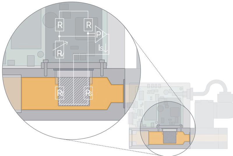
Two resistors with precisely defined temperature coefficients are positioned inside the fluid stream, joined by three external precision resistors to create a Wheatstone bridge circuit:
Flowing gas extracts thermal energy from the heated resistor $R_H$. The heating current required by the control circuit to sustain the specified temperature differential represents the primary measured variable. Combined with aerodynamic flow profiling within the fluidic channel and calibration standards, the mass flow per unit time is calculated with high repeatability.
Article 20092146 is built on the compact base block (00 or A1) with G 1/4" internal thread tapping and an integrated Type 2836 proportional control valve.
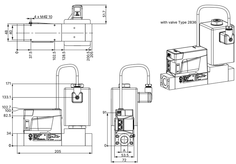
Thread depth specifications for standard body connection ports:
| Thread Designation (A) | Thread Depth [mm] |
|---|---|
| G 1/4 | 12 |
| NPT 1/4 | 11 |
| G 3/8 | 12 |
| NPT 3/8 | 11 |
| G 1/2 | 15 |
| NPT 1/2 | 14 |
| G 3/4 | 16 |
| NPT 3/4 | 15 |
| G 1 | 18 |
| NPT 1 | 16.8 |
Body Length for Flow Rates Above 1500 Nl/min
For versions utilizing base block A3 engineered for flow rates $Q_N > 1500\text{ Nl/min}$, the overall unit length increases by 30 mm.
Article 20092146 utilizes a 9-pin D-Sub subminiature plug for 24 V DC power distribution, analogue process signaling (4–20 mA setpoint and actual feedback), and binary input/output lines.
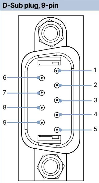
| Pin | D-Sub 9-Pin Assignment | Terminal Strip (6-Pin Variant Assignment) |
|---|---|---|
| 1 | Digital input | 24 V DC supply |
| 2 | GND (supply voltage and digital input) | GND supply |
| 3 | 24 V DC supply | Setpoint value input (+) |
| 4 | Relay contact, normally closed | Setpoint value input GND |
| 5 | Relay contact, common reference | Actual value output (+) |
| 6 | Setpoint value input (+) | Actual value output GND |
| 7 | Setpoint value input GND | — |
| 8 | Actual value output (+) | — |
| 9 | Actual value output GND | — |
| Housing | Cable shielding connection | — |
Pressure drop curves through the Type 8745 sensor body depend on gas density and base block design. The diagram below illustrates differential pressure curves with air.
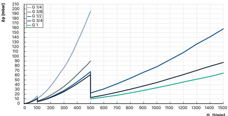
Differential pressure for alternative media is calculated using the following conversion formula: $$ \Delta P_{\mathrm{Gas}} = \Delta P_{\mathrm{Air}} \cdot \sqrt{\frac{\rho_{\mathrm{NGas}}}{\rho_{\mathrm{NAir}}}} $$
Nominal flow capabilities for common industrial gases across the Type 8745 platform (referenced to 1013.25 mbar abs and 0 °C):
| Gas Type | Min. $Q_N$ [Nl/min] | Max. $Q_N$ [Nl/min] |
|---|---|---|
| Acetylene | 20 | 320 (air calibrated from 65 Nl/min) |
| Ammonia | 8 | 1000 |
| Argon | 20 | 1600 |
| Carbon Dioxide (CO2) | 20 | 800 (1000 in MFM) |
| Air | 20 | 2500 |
| Methane | 20 | 1200 |
| Propane | 20 | 200 |
| Oxygen | 20 | 2500 |
| Nitrogen (N2) | 20 | 2500 |
Type 8745 belongs to the Bürkert EDIP (Efficient Device Integration Platform). Digital communication and parameter adjustment can be conducted using the Bürkert Communicator PC software via a CANopen-based service port.
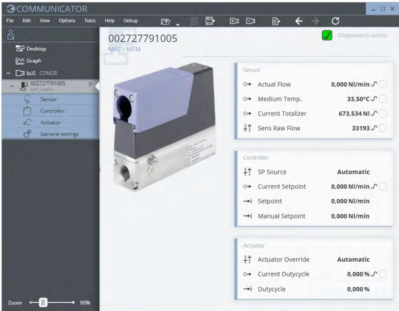
Key functions supported in Bürkert Communicator:
Micro-USB Connection Power Restriction
No external electrical power supply must be connected to the micro-USB service port. Power must be delivered strictly through the primary 24 V DC supply lines.
Configuration Memory Exchange
An optional memory card allows instant parameter transfer during hardware replacement. Swapping the memory card from a defective controller into a replacement device automatically restores operating configurations, provided both instruments share an identical article number.
| Description | Article Number |
|---|---|
| USB-büS interface set 2 (Type 8923) with büS stick, M12 cables, micro-USB adapter, and Y-splitter (0.7 m) | 772551 |
| Phoenix Class 2 power supply (Type 1573), 85–240 V AC / 24 V DC, 1.25 A, NEC Class 2 | 772438 |
| DIN rail power supply (Type 1573), 100–240 V AC / 24 V DC, 1 A, NEC Class 2 | 772361 |
| DIN rail power supply (Type 1573), 100–240 V AC / 24 V DC, 2 A, NEC Class 2 | 772362 |
| DIN rail power supply (Type 1573), 100–240 V AC / 24 V DC, 4 A | 772363 |
| D-Sub analogue adapter cable, open strand end, 5 m | 580882 |
| D-Sub analogue adapter cable, open strand end, 10 m | 580883 |
| 6-pin terminal strip (for standard analogue Type 8745) | On request |
| Configuration memory card | On request |
Explore similar products in our catalog