


PN25

BURKERT 20094619 Type 2921 is a manually operated 2/2-way globe valve featuring a DN 40 ASME BPE welded body, PTFE seat seal, PPS handwheel, PN25 pressure rating, and medium temperatures up to 185 °C.
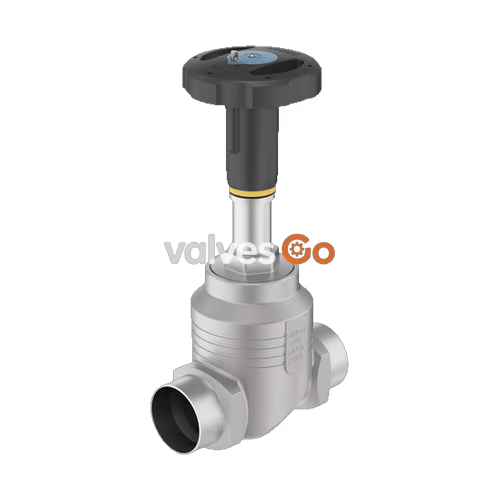
BURKERT 20094619 (Type 2921) is a manually operated 2/2-way globe valve configured for pure on/off shut-off duties across liquid, gaseous, and steam services. Built with a cast stainless steel 316L/CF3M straight-seat body, this configuration incorporates ASME BPE weld ends in DN 40 (NPS 1 1/2, pipe dimensions 38.1 x 1.65 mm), an internal seat diameter of 32 mm (1 1/4"), and a soft PTFE seat seal. The valve operates with medium flow directed underneath the seat (flow-to-open), shutting off against line pressure with leakage rate A conformity in accordance with DIN EN 12266-1.
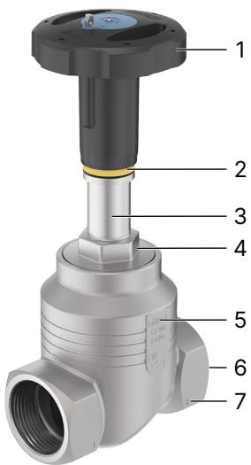
Actuation is controlled manually by a 45 mm diameter (Size S) polyphenylene sulphide (PPS) handwheel operating a D10 spindle drive. Stem sealing uses a proven, self-adjusting PTFE V-ring gland assembly backed by spring compensation, providing consistent stem sealing during frequent manual cycling. An integrated optical indicator delivers visual confirmation of the open/closed position directly above the handwheel mechanism.
| Parameter | Specification Details |
|---|---|
| Product Type | Type 2921 (2/2-way globe valve) |
| Article Number | 20094619 |
| Operating Mode | Manual on/off shut-off valve with swivel plate closure |
| Nominal Port Diameter | DN 40 (NPS 1 1/2) |
| Port Connection Size | Welded tube end 38.1 x 1.65 mm |
| Connection Standard | ASME BPE / DIN 11866 Series C / BS4825 |
| Seat Diameter | 32 mm (1 1/4") |
| Flow Coefficient Kv | 19.5 m³/h (water measurement according to DIN EN 60534-2-4) |
| Flow Coefficient Cv | 22.6 gpm |
| Operating Pressure Range | 0 bar(g) to 25 bar(g) |
| Nominal Pressure Class | PN 25 (DIN EN 1333), Class 150 (DIN EN 1759) |
| Seat Leakage Class | Rate A according to DIN EN 12266-1 (air test medium) |
| Medium Temperature Range | -10 °C to +185 °C |
| Ambient Temperature Range | -10 °C to +60 °C |
| Max. Viscosity | 600 mm²/s |
| Permitted Media | Steam, water, neutral gases, alcohols, oils, fuels, hydraulic fluids, saline solutions, lyes, organic solvents |
| Handwheel Diameter | 45 mm (Size S) |
| Handwheel Material | Polyphenylene sulphide (PPS) |
| Handwheel Pitch | 1.25 mm stroke advance per complete rotation |
| Spindle Interface | Spindle D10 |
| Product Identification | Data Matrix Code on type label |
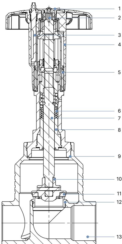
| Item No. | Element | Material |
|---|---|---|
| 1 | Cover | Polyamide (PA) |
| 2 | Screw | Stainless steel 1.4301 (304) |
| 3 | Locking device (optional) | Stainless steel 1.4305 (303) |
| 4 | Handwheel | Polyphenylene sulphide (PPS) |
| 5 | Visual position indicator with scale | Polyamide (PA) |
| 6 | Packing gland | Filled PTFE V-rings with spring compensation |
| 7 | Spindle | Stainless steel 1.4401 (316) / 1.4404 (316L) |
| 8 | Spindle guide | PEEK (for DN 15 to DN 50) |
| 9 | Housing seal | Graphite |
| 10 | Swivel plate | Stainless steel 1.4401 (316) / 1.4404 (316L) |
| 11 | Seat seal | PTFE (Polytetrafluoroethylene) |
| 12 | Valve seat with O-ring | Stainless steel 1.4571 (316Ti), EPDM |
| 13 | Valve body | Cast stainless steel 316L / CF3M |
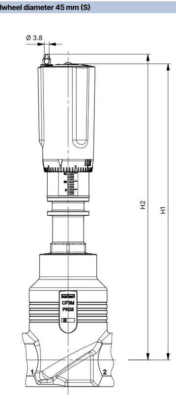
Actuator dimensions depend on the nominal pipe diameter and handwheel sizing. For DN 40 equipped with the 45 mm (Size S) PPS handwheel (Burkert article 20094619):
| Nominal Port DN | Nominal Port NPS | Handwheel Ø [mm] | Height H1 [mm] | Height H2 with Lock [mm] |
|---|---|---|---|---|
| 15 | 1/2 | 45 (S) | 217 | 224 |
| 20 | 3/4 | 45 (S) | 224 | 230 |
| 25 | 1 | 45 (S) | 228 | 234 |
| 32 | 1 1/4 | 45 (S) | 296 | 303 |
| 40 | 1 1/2 | 45 (S) / 110 (M) | 301 | 307 |
| 50 | 2 | 110 (M) | 307 | 313 |
| 65 | 2 1/2 | 160 (L) | 361 | 368 |
| 80 | 3 | 160 (L) | 369 | 375 |
| 100 | 4 | 160 (L) | 379 | 385 |
INFO
For article 20094619, the actuator handwheel diameter is 45 mm (Size S), giving an overall vertical height H1 of 301 mm (307 mm when fitted with the optional locking device).
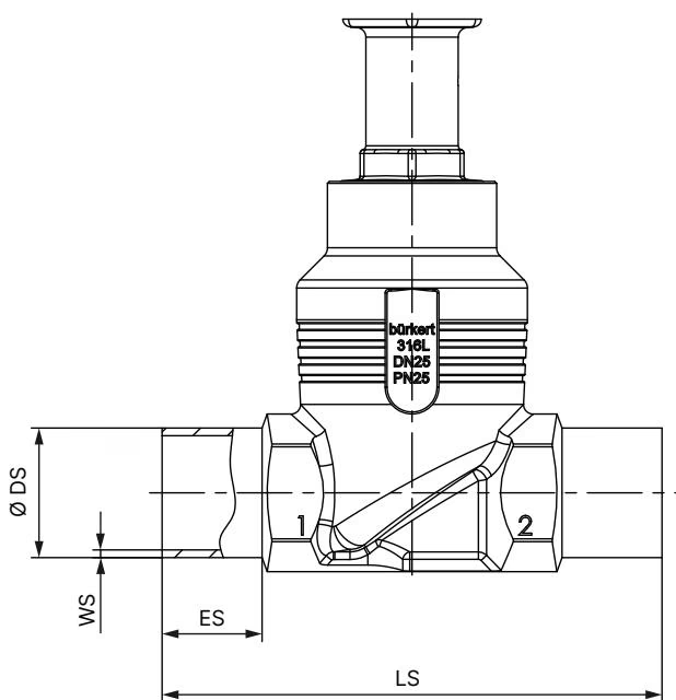
| Nominal Diameter NPS | Weld Length ES [mm] | Face-to-Face LS [mm] | Outer Tube Ø DS [mm] | Wall Thickness WS [mm] |
|---|---|---|---|---|
| 1/2 | 20 | 90 | 12.7 | 1.65 |
| 3/4 | 20 | 90 | 19.05 | 1.65 |
| 1 | 20 | 100 | 25.4 | 1.65 |
| 1 1/2 (DN 40) | 26 | 140 | 38.1 | 1.65 |
| 2 (DN 50) | 26 | 150 | 50.8 | 1.65 |
| 2 1/2 (DN 65) | 26 | 175 | 63.5 | 1.65 |
| 3 (DN 80) | 26 | 210 | 76.2 | 1.65 |
| 4 (DN 100) | 26 | 260 | 101.6 | 2.11 |
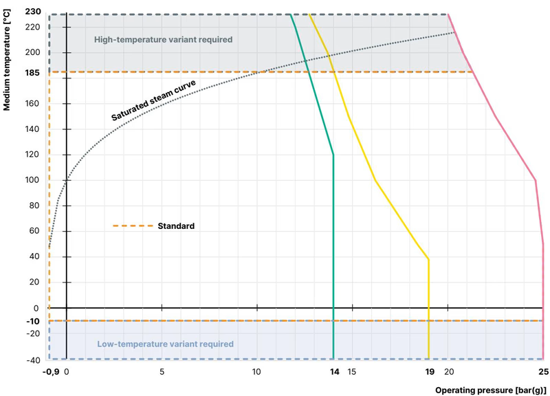
Maximum allowable working pressure derates as service temperature increases in line with flange and valve body design codes.
| Medium Temperature [°C] | Permissible Working Pressure [bar] |
|---|---|
| -10 to +50 | 25.0 |
| 100 | 24.5 |
| 150 | 22.4 |
| 200 | 20.3 |
| 230 | 19.0 |
| Medium Temperature [°C] | Permissible Working Pressure [bar] |
|---|---|
| -29 to +38 | 19.0 |
| 50 | 18.4 |
| 100 | 16.2 |
| 150 | 14.8 |
| 200 | 13.7 |
| 230 | 12.7 |
Operating Pressure and Temperature Limits
Article 20094619 features a PTFE seat seal rated for medium temperatures between -10 °C and +185 °C. For applications above 130 °C, verify system pressure against the derating curves above. Operating pressures must never exceed 25 bar(g).
Installation can take place in any orientation, preferably with the actuator upright. Before welding the valve body into the pipeline system, detach the actuator from the valve body to prevent heat transfer damage to internal seals.
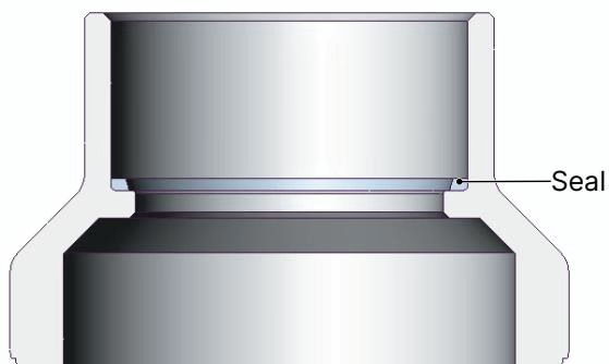
| Nominal Diameter DN | Tightening Torque [Nm] | Tolerance [Nm] |
|---|---|---|
| 10 / 15 | 45 | ±3 |
| 20 | 50 | ±3 |
| 25 | 60 | ±3 |
| 32 | 65 | ±3 |
| 40 | 65 | ±3 |
| 50 | 70 | ±3 |
| 65 | 100 | ±3 |
| 80 | 120 | ±5 |
| 100 | 150 | ±5 |
Pressure Hazard
De-energize pressure sources and drain or vent pipelines before conducting assembly, maintenance, or disassembly work. Do not reach into the valve body orifices during operation or testing.
Lubrication Restrictions
Use only lubricants compatible with the process media. In oxygen service, unsuitable grease creates an explosion hazard. Never use unapproved greases or pastes.
Turn the handwheel counter-clockwise to open the valve; turn clockwise to close. Handwheel size S advances 1.25 mm of stroke per full 360° rotation. When opened, the yellow optical indicator becomes visible beneath the handwheel shell.
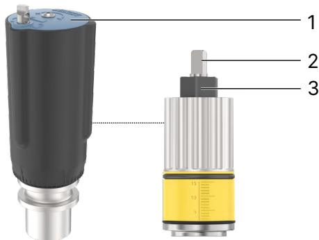
Both minimum and maximum stroke positions can be limited via an internal adjusting sleeve:
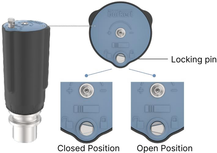
Accidental or unauthorized operation can be prevented by depressing the locking pin and rotating it 180°. For handwheel size S, 12 locking positions are available per revolution (every 30° indexing equals 0.1 mm of stroke). The locking pin incorporates a 3.8 mm diameter hole to accommodate a security padlock or safety lockout tagout clasp (article 93719475).
Locking Pin Leakage Limitation
When the valve is locked in the closed position, leakage class A cannot be unconditionally guaranteed under all dynamic process conditions. Locking serves as an operational deterrent, not a positive mechanical mechanical stop.
Under normal service conditions with non-abrasive fluids, the Type 2921 manual actuator is maintenance-free. Conduct an annual visual inspection of the body connection, packing gland area, and relief bore.
| Fault Observed | Probable Cause | Corrective Action |
|---|---|---|
| Valve does not seal tight at seat | Dirt or particulates lodged between seat and seal | Flush piping; install an upstream strainer/dirt trap |
| PTFE seat seal worn or deformed | Replace closure member assembly | |
| Reverse flow direction | Re-align valve; flow must enter below the seat | |
| Working pressure exceeds allowable limit | Adjust operating pressure to match type label limits | |
| Medium leaking from actuator relief bore | Spindle packing gland V-rings worn | Replace spindle packing gland set |
| Actuator loose on valve body | Thermal cycling or vibration loosening threads | Re-torque body connection to 65 ±3 Nm |
Explore similar products in our catalog



