PN25

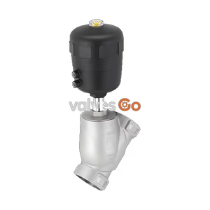
Burkert 20113210 (Type 2100) is a pneumatically operated 2/2-way angle seat valve with DN 15 clamp connection, Control Function A (NC), PTFE seat seal, PN 25 rating, and 5.4 m3/h Kv flow for liquids, gas, and steam.
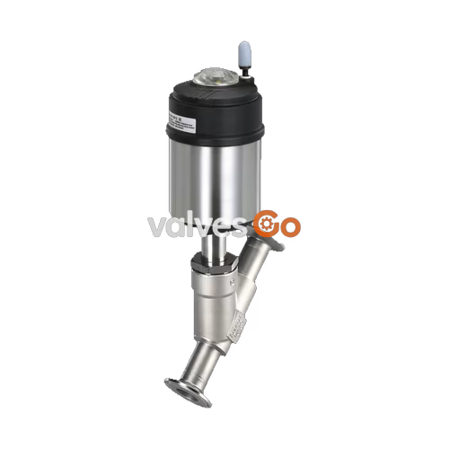
Burkert 20113210 (Type 2100) is a pneumatically operated 2/2-way angle seat valve from the ELEMENT series, specifically engineered for decentralized process automation in hygienic, utility, and demanding processing installations. Configured with Control Function A (normally closed by spring force), flow direction below the seat, and a DN 15 clamp process connection according to DIN 32676 series A, the valve regulates and isolates neutral gases, steam, water, alcohols, oils, fuels, hydraulic fluids, saline solutions, alkalis, and organic solvents.

Article 20113210 couples a cast stainless steel CF3M angle seat body with an actuator size Ø 70 mm (Size M) composed of a polyphenylene sulphide (PPS) cover and a 1.4561 (316Ti) stainless steel casing. The internal flow path delivers a water flow coefficient Kv of 5.4 m³/h at 1 bar differential pressure. Stem sealing is maintained by a self-adjusting PTFE V-ring packing gland with integrated spring compensation and a PEEK spindle guide, achieving tightness in accordance with DIN EN 12266-1 Leakage Rate A. All wetted materials meet Regulation (EC) 1935/2004 and FDA requirements according to manufacturer declarations, supporting full Clean-in-Place (CIP) and Steam-in-Place (SIP) procedures.
Burkert 20113210 operates under Control Function A (CFA). In its unpressurized rest position, the valve is held closed by actuator spring force acting on the spindle and the stainless steel swivel plate. Supplying compressed air (minimum 4.8 bar(g), maximum 10 bar(g)) to pilot air port 1 lifts the piston and retracts the swivel plate, opening the valve passage.
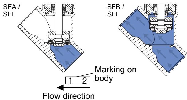
Because the process media enters below the valve seat, the operating line pressure assists the pneumatic actuator in opening the valve. This flow-to-open orientation prevents water hammer when controlling liquids, steam, and gases.
Operating Restriction: Liquid Media Direction
Valves with flow direction above the seat must never be used for liquid media due to the risk of destructive hydraulic shock (water hammer) that can burst pipelines and equipment. Burkert 20113210 is factory-configured for flow below the seat, which is suitable for liquids, steam, and gases up to 25 bar(g).
All construction materials for Burkert Type 2100 are selected for chemical compatibility and resistance to harsh process atmospheres. Lubricants utilized in the actuator and stem packing gland comply with NSF H1 classification.
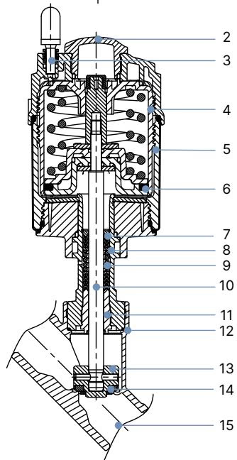
| Item | Component | Standard Material Execution | Notes for Article 20113210 |
|---|---|---|---|
| 1 | Ground terminal | Stainless steel 1.4301 / 1.4305 | ATEX variants only |
| 2 | Optical position indicator | Polysulfone (PSU) | Integrated visual indicator |
| 3 | Pilot air ports | Polypropylene (PP) push-in connector | External Ø 6 mm (1/4") push-in |
| 4 | Actuator cover | Polyphenylene sulphide (PPS) | ELEMENT design |
| 5 | Actuator casing | Stainless steel 1.4561 (316Ti) | High mechanical and chemical resistance |
| 6 | Piston seal | FKM | Pneumatic actuator sealing |
| 7 | Spring | Stainless steel 1.4310 | CFA closing spring pack |
| 8 | Pipe | Stainless steel 1.4401 (316) / 1.4404 (316L) | Internal guide tube |
| 9 | Packing gland | PTFE V-rings (filled) | Spring-compensated self-adjusting pack |
| 10 | Spindle | Stainless steel 1.4401 (316) / 1.4404 (316L) | Precision ground stem |
| 11 | Spindle guide | PEEK | Low-friction guidance |
| 12 | Body seal | Graphite (PTFE optional) | Bonnet-to-body seal |
| 13 | Swivel plate | Stainless steel 1.4401 (316) / 1.4404 (316L) | Articulated seal carrier |
| 14 | Seat seal | PTFE | Soft shut-off disc (PEEK optional) |
| 15 | Valve body | Stainless steel CF3M | Cast equivalent of 316L stainless steel |
Article 20113210 operates within the fluidic and pressure specifications detailed below. Data reflects flow direction below the seat with PTFE seat sealing.
| Technical Parameter | Specification Value |
|---|---|
| Valve Type | 2100 ELEMENT |
| Article Number | 20113210 |
| Control Function | Control Function A (normally closed by spring force) |
| Nominal Diameter (Port) | DN 15 |
| Seat Orifice Diameter | 15 mm |
| Flow Coefficient Kv (Water, +20 °C, 1 bar Δp) | 5.4 m³/h |
| Flow Direction | Flow to open (below seat) |
| Operating Pressure Range | 0 bar(g) to 25 bar(g) |
| Nominal Pressure Rating | PN 25 (DIN EN 1333) / Class 150 (DIN EN 1759) |
| Minimum Pilot Pressure | 4.8 bar(g) |
| Maximum Pilot Pressure | 10 bar(g) |
| Actuator Size | Ø 70 mm (Size M) |
| Process Connection Standard | Clamp DIN 32676 series A (matching DIN 11850 series 2 pipe) |
| Process Connection Dimensions | Flange Ø 34.0 mm, pipe Ø 19.0 x 1.5 mm (ID 16.0 mm) |
| Face-to-Face Body Length | 130 mm (clamp body LC) / 100 mm (valve body weld core LS) |
| Pneumatic Pilot Connection | Push-in connector for Ø 6 mm (1/4") outer diameter hose |
| Medium Temperature Range | -10 °C to +185 °C |
| Ambient Temperature Range | -10 °C to +60 °C (restricted by push-in pilot fitting) |
| Max. Permissible Viscosity | 600 mm²/s |
| Control Medium | Filtered air, neutral gases |
| Seat Leakage Rate | Leakage rate A according to DIN EN 12266-1 (air test) |
| Sound Pressure Level | < 70 dB(A) |
Dimensions depend on the actuator size and the process connection type. Burkert 20113210 combines a DN 15 body with an actuator size Ø 70 mm (M).
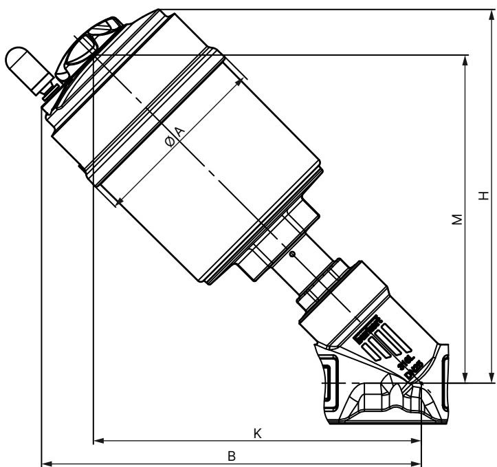
| Nominal Diameter DN | NPS | Actuator Size | Ø A [mm] | B [mm] | H [mm] | K/M [mm] |
|---|---|---|---|---|---|---|
| 15 | 1/2 | 50 (D) | 64.5 | 166 | 163 | 147 |
| 15 (20113210) | 1/2 | 70 (M) | 91.0 | 182 | 178 | 156 |
| 20 | 3/4 | 50 (D) | 64.5 | 174 | 171 | 155 |
| 20 | 3/4 | 70 (M) | 91.0 | 189 | 186 | 163 |
| 25 | 1 | 50 (D) | 64.5 | 175 | 173 | 156 |
| 25 | 1 | 70 (M) | 91.0 | 191 | 188 | 165 |
| 25 | 1 | 90 (N) | 120.0 | 229 | 228 | 203 |
| 32 | 1 1/4 | 70 (M) | 91.0 | 201 | 197 | 174 |
| 32 | 1 1/4 | 90 (N) | 120.0 | 243 | 242 | 217 |
| 40 | 1 1/2 | 70 (M) | 91.0 | 204 | 201 | 178 |
| 40 | 1 1/2 | 90 (N) | 120.0 | 246 | 245 | 220 |
| 50 | 2 | 70 (M) | 91.0 | 223 | 219 | 196 |
| 50 | 2 | 90 (N) | 120.0 | 262 | 261 | 236 |
Note: Dimensions B, H, K, and M represent maximum envelope values and may vary downward by up to 6 mm based on connection orifice and standard tolerances.
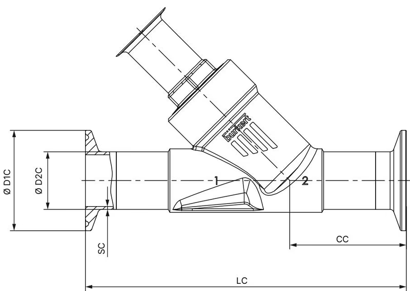
| Connection Standard | Nominal Size DN | Overall Length LC [mm] | Centerline Height CC [mm] | Clamp Flange Ø D1 C [mm] | Pipe Outer Ø D2 C [mm] | Wall Thickness SC [mm] |
|---|---|---|---|---|---|---|
| DIN 32676 Series A (20113210) | DN 15 | 130 | 49.5 | 34.0 | 19.0 | 1.5 |
| DIN 32676 Series A | DN 20 | 150 | 57.0 | 34.0 | 23.0 | 1.5 |
| DIN 32676 Series A | DN 25 | 160 | 58.5 | 50.5 | 29.0 | 1.5 |
| DIN 32676 Series A | DN 32 | 180 | 58.0 | 50.5 | 35.0 | 1.5 |
| DIN 32676 Series A | DN 40 | 200 | 69.5 | 50.5 | 41.0 | 1.5 |
| DIN 32676 Series A | DN 50 | 230 | 78.0 | 64.0 | 53.0 | 1.5 |
| DIN 32676 Series B | DN 15 | 156 | 49.0 | 50.5 | 21.3 | 1.6 |
| DIN 32676 Series B | DN 20 | 150 | 56.5 | 50.5 | 26.9 | 1.6 |
| DIN 32676 Series B | DN 25 | 160 | 58.0 | 50.5 | 33.7 | 2.0 |
| DIN 32676 Series B | DN 32 | 200 | 57.5 | 50.5 | 42.4 | 2.0 |
| DIN 32676 Series B | DN 40 | 200 | 69.0 | 64.0 | 48.3 | 2.0 |
| DIN 32676 Series B | DN 50 | 230 | 77.5 | 77.5 | 60.3 | 2.6 |
Maximum allowable operating pressure decreases as media temperature increases, determined by pressure vessel design standards DIN EN 12516-1 (PN 25) and ASME B16.34 (Class 150).
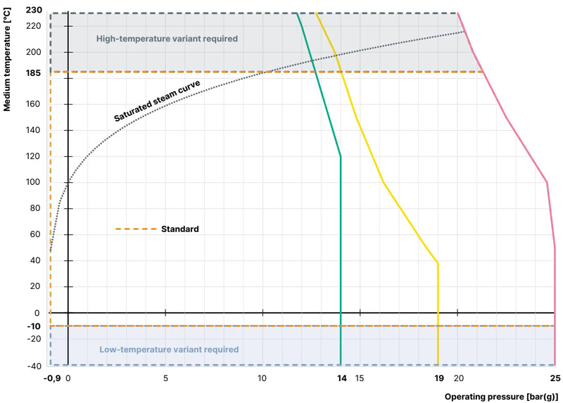
| Temperature [°C] | DIN EN 12516-1 / PN 25 Max. Pressure [bar] | ASME B16.34 Cl. 150 Max. Pressure [bar] | JIS B 2220 10K Max. Pressure [bar] |
|---|---|---|---|
| -10 to +38 / +50 | 25.0 | 19.0 | 14.0 |
| +100 | 24.5 | 16.2 | 14.0 |
| +150 | 22.4 | 14.8 | 13.4 |
| +200 | 20.3 | 13.7 | 12.4 |
| +230 | 19.0 | 12.7 | 11.7 |
Temperature Boundaries for Pneumatic Connections
When configured with push-in pneumatic connectors (as on article 20113210), ambient temperature must remain between -10 °C and +60 °C across the full media temperature range (-10 °C to +185 °C). If fitted with metal threaded G 1/8" pilot ports, the ambient limit extends to +100 °C.
Burkert 20113210 can be mounted in any orientation, although an upright actuator position is preferred to maximize service life and prevent sedimentation in the packing cavity.
Valve Position During Actuator Removal or Assembly
To prevent irreparable deformation of the seat seal and swivel plate, the valve must be in the fully open position whenever the actuator is removed from or threaded into the valve body. For Control Function A (normally closed), pressurize pilot air port 1 with compressed air at 5.0 bar to retract the plug before turning the body connection.
| Step | Procedure |
|---|---|
| 1. Secure Valve | Clamp the valve body firmly in a vice or holding fixture. |
| 2. Actuate Open | Apply 5.0 bar compressed air to pilot port 1 to open the valve plug fully. |
| 3. Apply Wrench | Place an open-end wrench on the wrench flat of the body connection hexagon. |
| 4. Disassemble / Assemble | Unscrew or torque down the actuator assembly. |
| 5. Tightening Torque | Torque the body connection to 45 Nm (+10/-5 Nm) for DN 15 (actuator sizes 40, 50, and 70 mm). |
The pneumatic pilot air ports can be continuously rotated through 360° to accommodate tight plant piping layouts.
Rotation Direction Restriction
Only rotate the actuator in the specified counterclockwise direction relative to the body connection hexagon while holding the body connection flat with a counter-wrench. Turning in the wrong direction loosens the body connection thread, causing media leakage.
Burkert 20113210 requires minimal maintenance due to its self-adjusting packing gland. Periodic visual inspections should be performed based on operational severity.
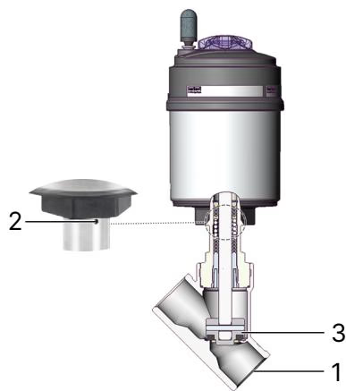
| Inspection Point | Observed Issue | Corrective Action |
|---|---|---|
| Media connectors (1) | Flange/clamp gasket leakage | Replace clamp gasket and re-tighten clamp band. |
| Relief bore (2) | Media leaking from weep hole on bonnet | Replace the packing gland pack or actuator assembly. |
| Swivel plate / seat (3) | Seat leakage through downstream line | Replace valve seat set / swivel plate assembly. |
| Malfunction | Possible Cause | Corrective Measure |
|---|---|---|
| Actuator does not switch | Pilot air connected to wrong port | Connect pilot air to port 1 for CFA (normally closed). |
| Pilot pressure insufficient | Verify pilot pressure is at least 4.8 bar(g) (up to 10 bar(g)). | |
| Operating line pressure too high | Reduce system operating pressure below 25 bar(g). | |
| Valve seat leaks | Dirt trapped between seal and seat | Flush line; install upstream strainer (mesh < 1 mm). |
| Valve seat seal worn or damaged | Disassemble actuator and install new swivel plate set. | |
| Reverse installation | Ensure pipeline flow matches direction arrow (flow below seat). | |
| Leakage at relief bore | Spindle packing gland worn | Replace stem packing gland using installation tool (683221). |
Burkert Type 2100 can be combined with ELEMENT automation modules to form the pre-tested valve system Type 8801-YE. Compatible top-mounted units include:
Explore similar products in our catalog