PWM Control

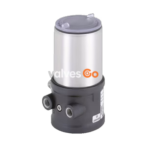
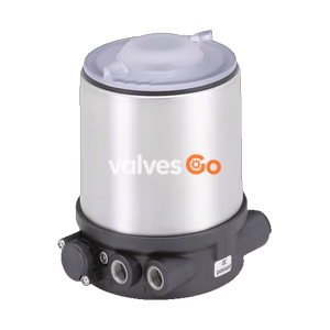
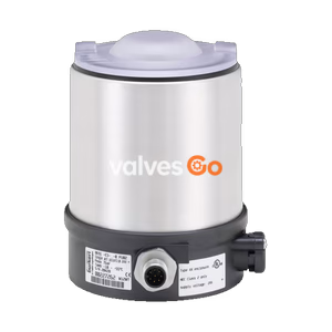
BURKERT Type 8697 pneumatic control unit (model 20127653) for decentralised automation of ELEMENT and CLASSIC process valves. Features inductive proximity switches, 24V DC, ATEX approval, and IP65/67.
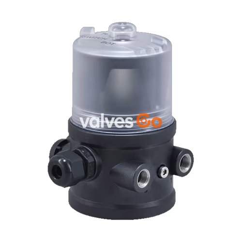
BURKERT 20127653 Type 8697 pneumatic control unit is designed for the decentralised automation of ELEMENT Type 21xx and CLASSIC Type 20xx pneumatic process valves. This specific model features inductive proximity switches (PNP) to record the valve position and an integrated pilot valve to control single-acting actuators. The design of the control unit and the actuator permits an integrated pilot air duct without external piping. As well as the electrical position feedback, the device status is displayed by LEDs on the pneumatic control unit itself. The housing is easy to clean and features proven IP65/IP67 protection and chemically resistant materials for use in hygienic processing in the food, beverage, and pharmaceutical industries.

Combined with Bürkert ELEMENT actuators, the pneumatic actuating system enables spring chamber aeration that avoids actuator chamber contamination from the environment.
| Property | Value |
|---|---|
| Body Material | PPS |
| Seal Material | EPDM |
| Cover Material | PC |
| Setting valve end position | Automatic (mechanical) |
| Manual override of pilot valve | Yes |
| Status display | Coloured LEDs |
| Operating voltage (Pilot valve) | 24 V DC ± 10 %, residual ripple 10 % DC, power consumption 1 W |
| Position feedback | 2x inductive proximity switch (24 V DC), PNP shutter (3-wire) with LEDs |
| Electrical connection | Cable gland M16 × 1.5 (cable ∅ 4...8 mm) with screw-type terminals |
| Control medium | Neutral gases, air, quality class according to ISO 8573-1 |
| Supply pressure | 3...7 bar |
| Air capacity | 7 lN/min (for aeration and ventilation) |
| Circuit function | Single-acting |
| Degree of protection | IP65/IP67 according to EN 60529, 4X according to NEMA 250 standard |
Note on Pressure
The supply pressure must be 0.5…1 bar above the minimum required pilot pressure of the valve actuator.
Explosion Protection (ATEX / IECEx)
North America (USA/Canada)
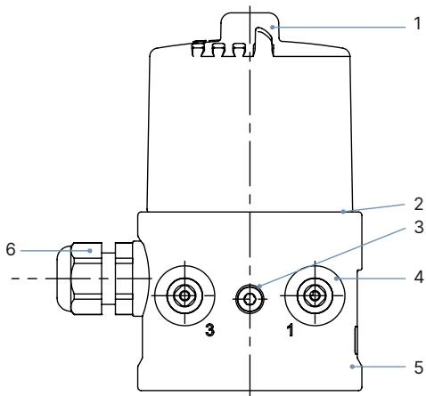
| No. | Element | Material |
|---|---|---|
| 1 | Cover | PC |
| 2 | Seals | EPDM |
| 3 | Screws | Stainless steel |
| 4 | Push-in connector / Threaded connection G 1/8 | POM/Stainless steel / Stainless steel |
| 5 | Basic housing | PPS |
| 6 | Cable gland | PA |
Mounting on ELEMENT process valve Types 21xx
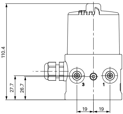
(Dimensions in mm, unless otherwise stated)
Cable Gland Variant (M16 × 1.5, screw terminal 1.5 mm²)
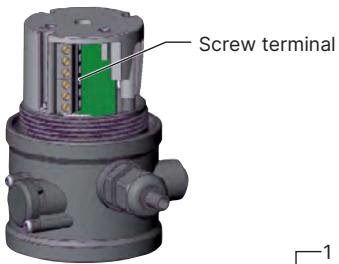
Terminal assignment with inductive proximity switch 3-wire 24 V DC PNP:
| Terminal | Configuration | External circuit |
|---|---|---|
| 1 | INI + (24 V DC) Supply | + 24 V DC |
| 2 | INI GND Supply | GND |
| 3 | INI Top OUT Output 1 | Output 1 |
| 4 | INI Bottom OUT Output 2 | Output 2 |
| 5 | Valve control 0/24 V DC | 0/24 V DC ± 10 % |
| 6 | Valve control GND | Residual ripple 10 % |
Electrical Safety
Risk of electric shock. Before reaching into the device, switch off the power supply and secure to prevent reactivation. Observe applicable accident prevention and safety regulations for electrical equipment.
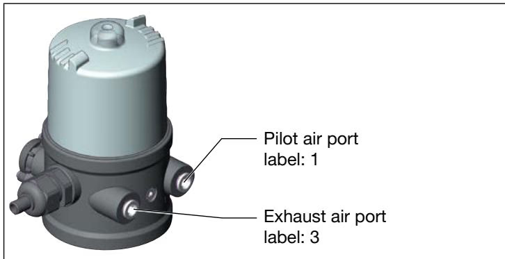
Procedure:
Exhaust Air Concept
In compliance with degree of protection IP67, an exhaust air line must be installed in the dry area. Keep the adjacent supply pressure always at least 0.5...1 bar above the pressure which is required to move the actuator to its end position.
Explore similar products in our catalog