


PN25

BURKERT 20133586 Type 2961 is a manual 2-way globe control valve (DN 80 welded, 88.9x2.3 mm, Kvs 100 m³/h). Features PEEK seat seal, equal percentage trim, PPS handwheel, and 0-10 bar operating pressure.
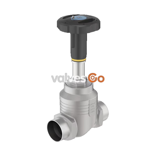
BURKERT 20133586 (Type 2961) is a manually operated 2-way globe control valve designed for regulating liquid, steam, and gas media in industrial process systems. Configured with an 88.9 x 2.3 mm welded port connection complying with DIN EN ISO 1127, ISO 4200, and DIN 11866 Series B (DN 80 / NPS 3), this valve features an exchangeable 80 mm stainless steel seat and an equal percentage control cone providing a theoretical rangeability of 50:1. Operating with a flow-to-open orientation (flow below the seat), BURKERT 20133586 delivers a Kvs rating of 100 m³/h (Cv 116.5 gpm) across an operating pressure span of 0 to 10 bar(g).
The manual actuator is constructed from polyphenylene sulphide (PPS) and incorporates a 160 mm diameter handwheel (size L), a D22 spindle interface, and an optical position indicator with a reproducible stroke scale. Tight shut-off is ensured by a PEEK soft seat seal meeting DIN EN 60534-4 Leakage Class VI, eliminating the need for an additional upstream isolation valve in compatible systems. Spindle sealing is maintained by a spring-compensated, filled PTFE V-ring gland that requires no manual retightening. The investment cast 316L (CF3M) stainless steel globe body complies with PN 25 (DIN EN 1333) and ASME Class 150 pressure ratings, covering a continuous medium temperature span from -10 °C to +185 °C.

| Parameter | Specification for Article 20133586 |
|---|---|
| Product Type | Manually operated 2-way globe control valve |
| Type Family | 2961 |
| Article Number | 20133586 |
| Pipe Size / Port Connection | DN 80 (NPS 3) welded, pipe dimensions 88.9 x 2.3 mm |
| Connection Standard | DIN EN ISO 1127 / ISO 4200 / DIN 11866 Series B |
| Nominal Seat Diameter | 80 mm (3") |
| Flow Coefficient Kvs (Water) | 100 m³/h |
| Flow Coefficient Cv | 116.5 gal/min |
| Flow Characteristic | Equal percentage, theoretical rangeability 50:1 |
| Flow Direction | Flow to open (under seat) |
| Operating Pressure Range | 0 bar(g) to 10 bar(g) |
| Nominal Pressure Class | PN 25 (DIN EN 1333), Class 150 (DIN EN 1759) |
| Seat Leakage Rate | Leakage class VI according to DIN EN 60534-4 (PEEK seal) |
| Medium Temperature Range | -10 °C to +185 °C |
| Ambient Temperature Range | -10 °C to +60 °C |
| Storage Temperature | -20 °C to +65 °C |
| Maximum Fluid Viscosity | 600 mm²/s |
| Actuator Size / Handwheel | Size L (handwheel diameter 160 mm, PPS) |
| Stroke Pitch per Revolution | 2.0 mm |
| Valve Stroke (Nominal) | 27 mm |
| Actuator Interface | Spindle D22 |
| Position Indicator | Optical with reproducible stroke scale (50 increments/rev) |
| Test Certificate | Manufacturer inspection certificate 3.1 enclosed |
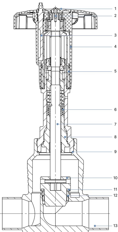
| Item | Component | Material |
|---|---|---|
| 1 | Cover | Polyamide (PA) |
| 2 | Screw | Stainless steel 1.4301 |
| 3 | Locking device (optional) | Stainless steel 1.4305 |
| 4 | Handwheel | Polyphenylene sulphide (PPS) |
| 5 | Visual position indicator with scale | Polyamide (PA) |
| 6 | Packing gland | Filled PTFE V-rings, spring-compensated |
| 7 | Stem | Stainless steel 1.4401 or 1.4404 |
| 8 | Spindle guide | Stainless steel 1.4404 (316L), PTFE filled |
| 9 | Housing seal | Graphite |
| 10 | Control cone | Stainless steel 1.4571 |
| 11 | Seat seal | PEEK (Polyetheretherketone) |
| 12 | Valve seat with O-ring | Stainless steel 1.4571, EPDM |
| 13 | Valve body | Cast stainless steel 316L / CF3M |
| Nominal Diameter DN | Nominal Size NPS | Handwheel Size | Handwheel ∅ [mm] | Height H1 [mm] | Height H2 (with locking) [mm] |
|---|---|---|---|---|---|
| 15 | 1/2 | S | 45 | 217 | 224 |
| 20 | 3/4 | S | 45 | 224 | 230 |
| 25 | 1 | S | 45 | 228 | 234 |
| 32 | 1 1/4 | M | 110 | 296 | 303 |
| 40 | 1 1/2 | M | 110 | 301 | 307 |
| 50 | 2 | M | 110 | 307 | 313 |
| 65 | 2 1/2 | L | 160 | 361 | 368 |
| 80 | 3 | L | 160 | 369 | 375 |
| 100 | 4 | L | 160 | 379 | 385 |
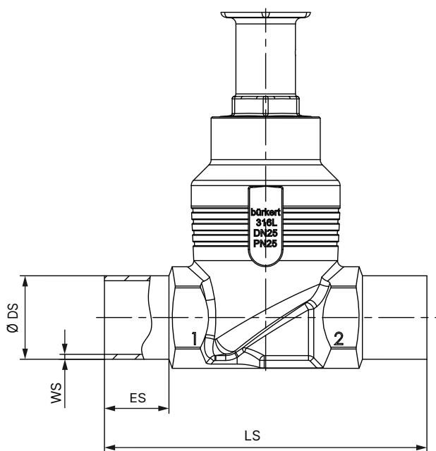
| Nominal Diameter DN | ES [mm] | LS [mm] | Pipe Outer Diameter ∅ DS [mm] | Wall Thickness WS [mm] |
|---|---|---|---|---|
| 10 | 20 | 90 | 17.2 | 1.6 |
| 15 | 20 | 90 | 21.3 | 1.6 |
| 20 | 20 | 100 | 26.9 | 1.6 |
| 25 | 26 | 130 | 33.7 | 2.0 |
| 32 | 26 | 140 | 42.4 | 2.0 |
| 40 | 26 | 150 | 48.3 | 2.0 |
| 50 | 26 | 175 | 60.3 | 2.0 |
| 65 | 26 | 210 | 76.1 | 2.3 |
| 80 | 26 | 230 | 88.9 | 2.3 |
| 100 | 26 | 260 | 114.3 | 2.6 |
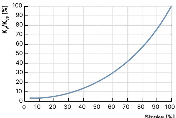
BURKERT 20133586 follows an equal percentage characteristic according to DIN EN 60534-2-4 with a theoretical rangeability of 50:1. For valve seat diameters greater than 10 mm, the minimum controllable flow rate (KvR) is evaluated at 5% of the stroke.
| Stroke [%] | 5% | 10% | 20% | 30% | 40% | 50% | 60% | 70% | 80% | 90% | 100% (Kvs) |
|---|---|---|---|---|---|---|---|---|---|---|---|
| Kv [m³/h] | 2.5 | 3.4 | 6.3 | 10.7 | 16.0 | 27.0 | 42.5 | 58.0 | 73.0 | 87.0 | 100.0 |
| Pipe Size | Seat Size [mm] | Handwheel | Stainless Steel Seat [bar] | PTFE Seat Seal [bar] | PEEK Seat Seal [bar] |
|---|---|---|---|---|---|
| DN 80 | 50 | 160 (L) | 25 (Class II) | 25 (Class VI) | 20 (Class VI) |
| DN 80 | 65 | 160 (L) | 24 (Class II) | 24 (Class VI) | 14 (Class VI) |
| DN 80 | 80 | 160 (L) | 16 (Class II) | 16 (Class VI) | 10 (Class VI) |
Operating Pressure Limit with PEEK Seat
For article 20133586 with an 80 mm seat diameter and PEEK seat seal, the maximum permissible differential operating pressure is limited to 10 bar(g) (1.0 MPa) to guarantee DIN EN 60534-4 Leakage Class VI tightness.
According to DIN EN 12516-1 (PN 25) and ASME B16.34 (Class 150), maximum body pressure decreases with rising fluid temperature:
| Standard / Rating | -10 °C to +50 °C | +100 °C | +150 °C | +200 °C | +230 °C |
|---|---|---|---|---|---|
| DIN EN 12516-1 (PN 25) | 25.0 bar | 24.5 bar | 22.4 bar | 20.3 bar | 19.0 bar |
| ASME B16.34 (Class 150) | 19.0 bar (-29 to +38 °C) | 16.2 bar | 14.8 bar | 13.7 bar | 12.7 bar |
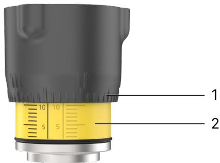
Turning the handwheel counterclockwise opens the valve by retracting the spindle and parabolic control cone away from the seat. Turning clockwise drives the spindle down to close against the fluid stream.
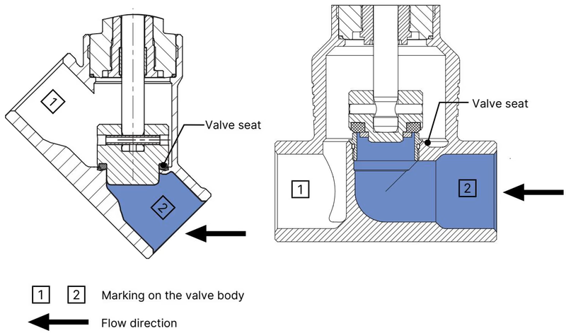
Seated Tightness Under Lock
When locking the handwheel in the closed position, Leakage Class VI shut-off cannot be guaranteed under all dynamic process variations. Handwheel closure force must be maintained to establish full seal compliance.
Depressurize Before Servicing
Depressurize the piping system and drain or vent all process fluids before loosening any body or actuator fittings. Failure to do so poses severe risk of personal injury.
To weld the valve body into the pipe run without damaging internal elastomeric and polymeric parts:
| Body Connection Size DN | Tightening Torque [Nm] | Tolerance [Nm] |
|---|---|---|
| 10 / 15 | 45 | ±3 |
| 20 | 50 | ±3 |
| 25 | 60 | ±3 |
| 32 | 65 | ±3 |
| 40 | 65 | ±3 |
| 50 | 70 | ±3 |
| 65 | 100 | ±3 |
| 80 | 120 | ±5 |
| 100 | 150 | ±5 |
Pipeline Vibration and High Temperature Check
In piping installations subjected to mechanical vibration or temperatures exceeding 140 °C, check the actuator-to-body threaded joint periodically to verify that the torque remains within the 120 Nm ± 5 Nm specification.
Under standard operating conditions, the PPS manual actuator is maintenance-free. Perform an annual visual inspection of the valve assembly. If particulate-laden or abrasive fluids are handled, shorten inspection intervals accordingly.
| Malfunction | Possible Cause | Corrective Action |
|---|---|---|
| Valve does not seal tightly | Particulate debris lodged between seat and PEEK seal | Flush line and install an upstream strainer / dirt trap |
| PEEK seat seal worn or eroded | Replace closure member (control cone assembly) | |
| Incorrect flow direction installed | Verify flow direction arrow on body; flow must enter below seat | |
| Operating pressure exceeds 10 bar(g) | Verify system differential pressure conforms to type label limits | |
| Medium leakage at relief bore | Spindle packing gland V-rings worn | Replace packing gland seal kit |
Replacement seal sets and wear parts are identified using the 8-digit article number 20133586 from the actuator nameplate.
Explore similar products in our catalog



