Transit-Time Ultrasonic

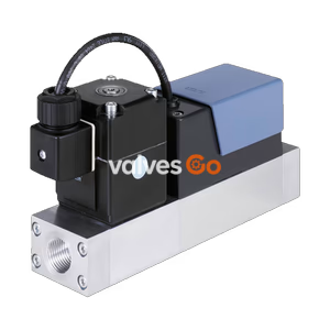
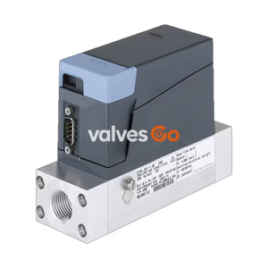
Burkert Type 8746 (SKU 20142867) Mass Flow Controller/Meter for Ar argon. Features 600 Nl/min nominal flow, 24V DC, G 1/2" port, 4-20 mA signal, and IP65 protection.
BURKERT Type 8746 (SKU 20142867) is a Mass Flow Controller (MFC) / Mass Flow Meter (MFM) for gases, suitable for a wide range of applications, e.g., metal and glass manufacturing or processing, fermentation processes, test benches, or filling systems and packaging machines. The specific SKU 20142867 is configured for Ar argon with a nominal flow rate of 600 Nl/min, featuring a G 1/2" internal thread, 24V DC supply, and 4-20 mA analogue communication.
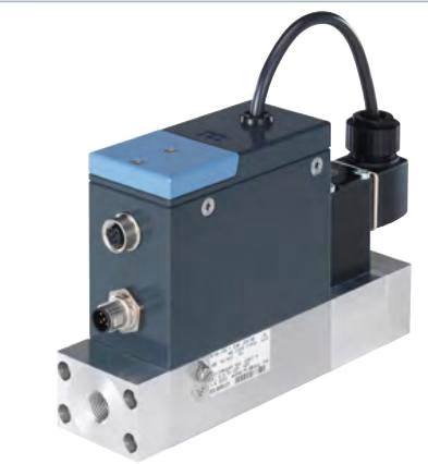
Type 8746 is available in two variants: a variant with several analogue or digital communication interfaces and a variant with a pure CANopen-based interface. The thermal inline sensor is located directly in the main flow and achieves fast response times and a high level of measuring accuracy with long-term stable calibration. As the actuator, a Bürkert direct-acting, electromagnetic proportional valve or motor valve guarantees high response sensitivity.
| Product properties | Description |
|---|---|
| Seal | FKM or EPDM (depending on gas) |
| Housing | Die-cast aluminium (painted) |
| Base block | Aluminium or stainless steel 1.4404/316L |
| Wetted parts (sensor) | Stainless steel 1.4404/316L, Al₂O₃, PPS GF40, epoxy resin, silicon, silicon nitride |
| Operating voltage | 24 V DC (±10% voltage tolerance, ±2% residual ripple) |
| Operating medium | Neutral, pure gases (others on request) |
| Medium temperature | -10 °C to +70 °C (-10 °C to +60 °C with oxygen) |
| Degree of protection | IP65 |
| Ambient temperature | -10 °C to +50 °C (higher temperatures on request) |
Type 8746 can be configured as MFC or MFM as required. The MFC variant uses direct-acting proportional valves of the 287x series. These electromagnetic proportional valves are normally closed and stand for highest measuring accuracy and repeatability with settling times resp. response times of a few hundred milliseconds.
| Performance data | Description |
|---|---|
| Nominal flow range (Q_N) | MFC: 20...1500 I_N/min (N₂) MFM: ≤ 2500 I_N/min (N₂) |
| Operating pressure | MFM: max. 25 bar MFC: max. 25 bar (depends on medium and nominal valve size) |
| Measuring accuracy | ±1.5% MV ±0.3% FS (under calibration conditions) |
| Repeatability | ±0.1% FS |
| Turndown ratio | 1:50 |
| Settling time (t95) | < 500 ms |
| Power consumption | MFM: max. 2 W MFC: max. 10.5...29.5 W (depending on valve type) |
Type 8746 with electromotive proportional valve is especially suitable for applications with high inlet pressures up to 22 bar or high flow rates (with low pressure loss). Thanks to their very low holding power, these valves can drastically reduce a system’s energy consumption. When de-energised, the motor valves remain in position.
| Performance data | Description |
|---|---|
| Nominal flow range (Q_N) | 20...2500 I_N/min (N₂) |
| Operating pressure | MFM: max. 25 bar MFC: max. 25 bar |
| Measuring accuracy | ±2% MV ±0.5% FS (under calibration conditions) |
| Repeatability | ±0.5% FS |
| Turndown ratio | 1:50 |
| Settling time (t95) | < 5 s |
| Power consumption | MFM: max. 2 W MFC: max. 10.5 W (Valve holding power is < 1 W) |
M12 socket, 5-pin (A-coded):
M12 plug, 5-pin (A-coded):
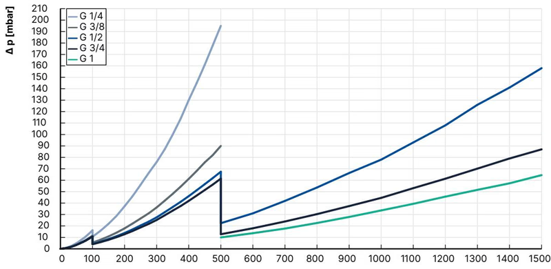
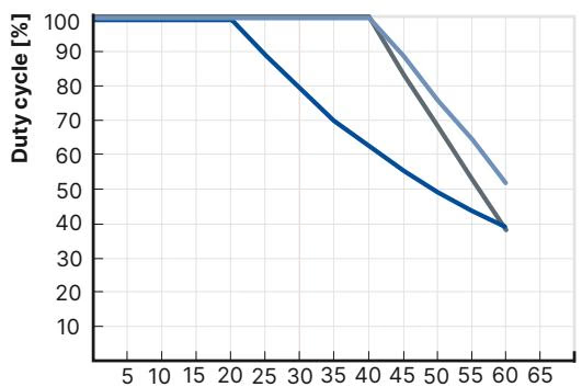
The diagram shows an example of the pressure loss curves with air flowing through. To determine the pressure loss of other gases, the corresponding air equivalent must first be calculated and the base block used for the other gas must be taken into account.
| Gas | Min. Q_N [l/min] | Max. Q_N [l/min] |
|---|---|---|
| Acetylene | 20 | 320 (from 65 l/min with air calibration) |
| Ammonia | 8 | 1000 |
| Argon | 20 | 1600 |
| Carbon dioxide | 20 | 800 |
| Air | 20 | 2500 |
| Methane | 20 | 1200 |
| Propane | 20 | 200 |
| Oxygen | 20 | 2500 |
| Nitrogen | 20 | 2500 |
(All values refer to 1013.25 mbar abs and 273.15 K / 0 °C)
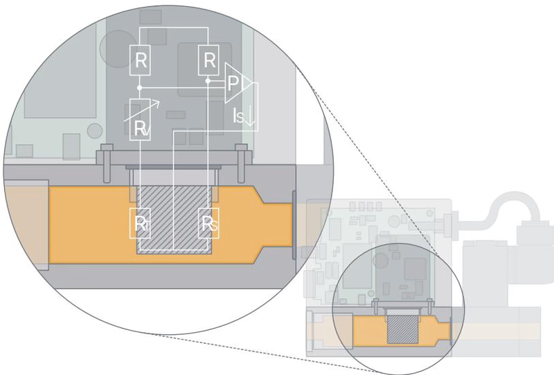
This sensor works as a hot-film anemometer in the so-called CTA operational mode (Constant Temperature Anemometer). Two resistors with a precisely specified temperature coefficient located directly in the media flow and three further resistors are connected to form a measuring bridge. The first resistor in the gas flow measures the fluid temperature, while the second, low-value resistor is always heated just enough to keep it at a fixed, specified excess temperature with respect to the fluid temperature. The heating current required for this purpose is a measure of heat dissipation and represents the primary measured quantity.
Safety Information
Explore similar products in our catalog