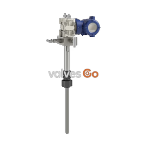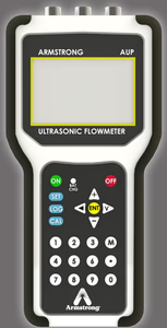
Transit-Time Ultrasonic

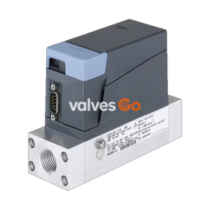
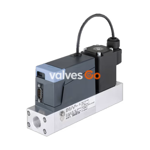
BURKERT 20143453 Type 8741 Mass Flow Controller/Meter for Helium. Features 60 Nl/min flow rate, 24 V DC, G 1/4" internal thread, and 4-20 mA output.
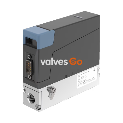
BURKERT 20143453 Type 8741 mass flow controller (MFC) / mass flow meter (MFM) for gases is suitable for a variety of applications. This specific model is configured for Helium (He) with a nominal flow range of 60 Nl/min, featuring an aluminium body, EPDM seals, G 1/4" internal thread, and a 4-20 mA analogue output signal. The thermal MEMS sensor is located directly in the gas stream and therefore achieves very fast response times. As an actuator, a Bürkert direct-acting proportional valve guarantees high response sensitivity.
Key features of the Type 8741 series include:
| Product Properties | Description |
|---|---|
| Material | |
| Seal | EPDM (Ethylene-propylene-diene rubber) |
| Housing | PC (polycarbonate) |
| Base block | Aluminium |
| Wetted parts | Stainless steel 1.4310/302, 1.4113/434, 1.4305/303 |
| Total weight | Approx. 500 g (aluminium base block) |
| Performance Data | |
| Nominal flow range | 60 Nl/min (He helium) |
| Operating pressure | Max. 25 bar |
| Measuring accuracy | ±0.8% MV ±0.3% FS (under calibration conditions) |
| Repeatability | ±0.1% FS |
| Turndown ratio | 1:50 |
| Settling time (t95) | <300 ms |
| Electrical Data | |
| Operating voltage | 24 V DC |
| Residual ripple | ±2% |
| Voltage tolerance | ±10% |
| Environment and Installation | |
| Installation position | Horizontal or vertical |
| Ambient temperature | -10 °C...+50 °C |
| Degree of protection | IP20 |
Note
The approvals and conformities listed below must be stated when making enquiries. Not all available variants can be supplied with the below mentioned approvals or conformities.
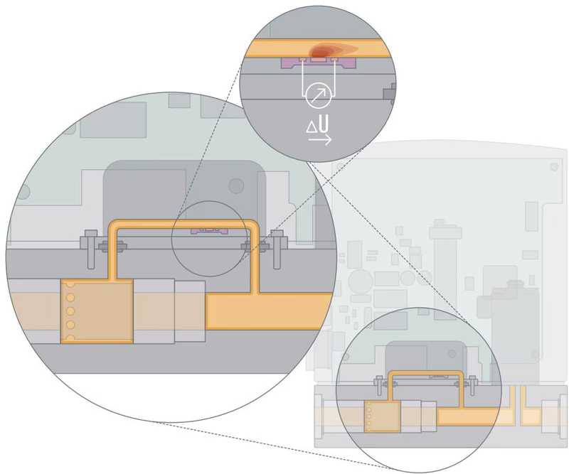
The measured values are recorded in a secondary channel. A laminar flow element in the main channel creates a slight pressure drop. A part of the gas flow is thereby directed into the secondary channel. The sensor located there records the mass flow as a temperature difference. The measurement is performed in a specially shaped flow channel whose wall contains a silicon chip with an etched membrane. A heating resistor and 2 temperature sensors, one upstream and one downstream, are attached on this membrane.
If the heating resistor is fed with a constant voltage, the differential voltage of the temperature sensors indicates the flow rate of the gas flowing over the chip.
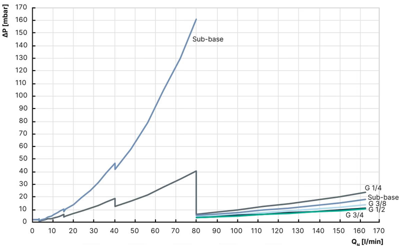
The diagram shows an example of the pressure loss curves with air flowing through. To determine the pressure loss of other gases, the corresponding air equivalent must first be calculated and the base block used for the other gas must be taken into account.
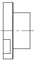
| Thread (A) | Thread depth [mm] |
|---|---|
| G 1/4, NPT 1/4 | 12 |
| G 1/8, NPT 1/8 | 12 |
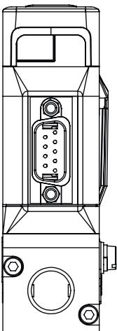
| D-Sub plug, 9-pin | Pin | Assignment |
|---|---|---|
| 1 | Digital input | |
| 2 | GND (for supply voltage and digital input) | |
| 3 | 24 V | |
| 4 | Relay, normally closed contact | |
| 5 | Relay, reference contact | |
| 6 | Set-point value input + | |
| 7 | Set-point value input GND | |
| 8 | Actual value output + | |
| 9 | Actual value output GND | |
| Housing | Shielding |
Type 8741 serves as a compact and technically up-to-date replacement for legacy devices (Type 8701, 8711, 8703, 8713).
Installation Compatibility
For electrical adaptation, adapter cables are available to connect the new device using existing analogue/D-Sub, PROFIBUS/M12, or RS422/RS485 connections.
Explore similar products in our catalog