


PN25

BURKERT 361793 (Type 2100) is a pneumatically operated 2/2-way angle seat valve with DN 50 weld ends, stainless steel CF3M body, PTFE seat seal, normally closed function, and 0-25 bar rating.
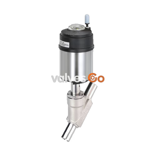
BURKERT 361793 (Type 2100) is a pneumatically operated 2/2-way angle seat valve from the ELEMENT series configured with a DN 50 weld-end connection, normally closed (Control Function A) switching state, and flow direction below the seat. Built with a cast stainless steel CF3M body and a 130 mm (size P) pneumatic actuator, the valve is engineered for demanding industrial steam, water, gas, and hygienic fluid applications requiring high flow capacity and tight shut-off up to 25 bar(g).

Equipped with a self-adjusting PTFE V-ring packing gland with spring compensation, BURKERT 361793 maintains reliable stem sealing over extended operational cycles. The valve complies with EC Regulation 1935/2004 for food contact, supports CIP and SIP cleaning procedures, and is rated for medium temperatures ranging from -10 °C to +185 °C.
BURKERT 361793 operates with control air between 5.0 and 7.0 bar(g) supplied to a G 1/8" internal thread pilot port. Medium flow enters under the seat, eliminating hydraulic shock during closure in liquid systems.
| Specification Parameter | Technical Value |
|---|---|
| Article Number | 361793 |
| Valve Type Family | Type 2100 (ELEMENT Series) |
| Valve Construction | Complete valve assembly |
| Nominal Diameter | DN 50 (NPS 2) |
| Flow Coefficient (Kv water) | 62 m³/h |
| Process Connection Type | Welded pipe end |
| Applicable Pipe Standards | ISO 4200 / DIN EN ISO 1127 / DIN 11866 Series B |
| Nominal Pressure Class | PN 25 (DIN EN 1333) / Class 150 (DIN EN 1759) |
| Maximum Operating Pressure | 25 bar(g) (limited to 20 bar for group 1 compressible media) |
| Control Function | CFA (Normally closed by spring force) |
| Pilot Medium | Compressed air, neutral gases |
| Minimum Pilot Pressure | 5.0 bar(g) |
| Maximum Pilot Pressure | 7.0 bar(g) |
| Pilot Air Connection | G 1/8" internal thread |
| Seat Leakage Rate | Leakage rate A per DIN EN 12266-1 (Air test medium) |
| Medium Temperature Range | -10 °C to +185 °C |
| Ambient Temperature Range | -10 °C to +100 °C |
| Maximum Kinematic Viscosity | 600 mm²/s |
Pressure Derating Under Operating Temperature
Operating pressure must be derated according to DIN EN 12516-1 / PN 25 standards: 25.0 bar from -10 °C to +50 °C; 24.5 bar at 100 °C; 22.4 bar at 150 °C; 20.3 bar at 200 °C; and 19.0 bar at 230 °C. For compressible fluids of group 1 under the Pressure Equipment Directive 2014/68/EU, maximum allowable pressure is restricted to 20 bar(g).
Wetted metallic surfaces are constructed from austenitic stainless steels CF3M and 1.4404 (316L), providing resistance to aggressive clean steam, organic solvents, deionized water, and chemical wash solutions.
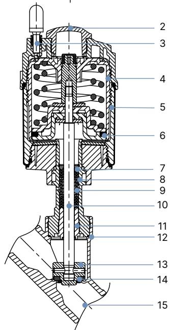
| Item No. | Component Element | Material Specification |
|---|---|---|
| 1 | Ground terminal | Stainless steel 1.4301 / 1.4305 (included on ATEX variants) |
| 2 | Optical position indicator | Polysulfone (PSU) |
| 3 | Pilot air port | Stainless steel 1.4305 / G 1/8" thread bushing (or PP push-in connector) |
| 4 | Actuator cover | Polyphenylene sulphide (PPS) |
| 5 | Actuator casing | Stainless steel 1.4561 (316Ti) |
| 6 | Piston seal | FKM |
| 7 | Actuator spring | Stainless steel 1.4310 |
| 8 | Spindle pipe | Stainless steel 1.4401 (316) / 1.4404 (316L) |
| 9 | Packing gland | Filled PTFE V-rings with spring compensation |
| 10 | Valve spindle | Stainless steel 1.4401 (316) / 1.4404 (316L) |
| 11 | Spindle guide | Polyether ether ketone (PEEK) |
| 12 | Body seal | Graphite (PTFE optional) |
| 13 | Swivel plate | Stainless steel 1.4401 (316) / 1.4404 (316L) |
| 14 | Seat seal | PTFE (PEEK optional) |
| 15 | Valve body | Cast stainless steel CF3M (equivalent to AISI 316L) |
All lubricants utilized within the packing gland assembly and pneumatic actuator chamber comply with NSF H1 food-grade certification.
BURKERT 361793 incorporates weld ends configured to ISO 4200, DIN EN ISO 1127, and DIN 11866 Series B dimensions.
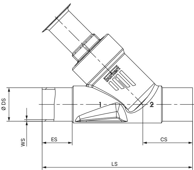
| Nominal Diameter | Port Outer Ø (DS) | Port Inner Ø | Wall Thickness (WS) | Weld Length (ES) | Centerline Height (CS) | Face-to-Face (LS) |
|---|---|---|---|---|---|---|
| DN 50 | 60.3 mm | 56.3 mm | 2.0 mm | 26 mm | 50 mm | 175 mm |
| Actuator Size | Actuator Outer Ø (A) | Height Dimension B | Height Dimension H | Body Clearance K/M |
|---|---|---|---|---|
| 130 (P) | 159 mm | 312 mm | 312 mm | 273 mm |
Dimensions B, H, K, and M represent maximum envelope values and may be up to 6 mm lower depending on the specific connection configuration.
In Control Function A (normally closed), the internal spring package exerts downward axial force through the valve spindle onto the swivel plate, sealing the PTFE seat disc against the seat orifice. Introducing pilot air (minimum 5.0 bar) into pilot port 1 drives the piston upward against the return springs, retracting the swivel plate into the fully open position.
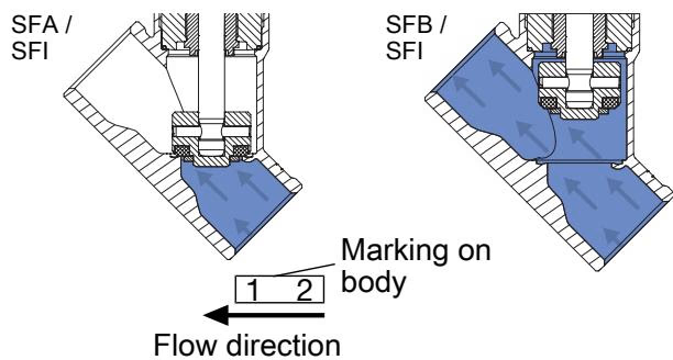
Operating medium enters under the seat disc (flow-to-open configuration). The process pressure assists in pushing the valve plug open during actuation, preventing line pressure surges and water hammer.
Liquid Media Operating Restriction
Valves with flow direction above the seat must not be used on liquid media because rapid closing can cause devastating pressure shocks and pipe ruptures. Flow direction below the seat is the mandated configuration for liquid and condensing media.
BURKERT 361793 integrates with the modular ELEMENT decentralized automation platform, allowing direct mounting of control heads and position transmitters without external tubing:
When combined with control heads, overall valve assembly height for DN 50 with actuator size 130 (P) increases to 351 mm (with Type 8690) or 374 mm (with Type 8691).
Installation may proceed in any mounting orientation, although upright vertical placement of the actuator is recommended to maximize seal life.
Actuator Disassembly Prior to Pipe Welding
During installation of welded valve bodies, heat conduction from orbital or manual welding will damage internal polymer seals. The pneumatic actuator must be unscrewed from the body before welding in-line:
| Nominal Diameter | Actuator Size | Tightening Torque | Torque Tolerance |
|---|---|---|---|
| DN 50 | 130 (P) / 90 (N) / 70 (M) | 70 Nm | +10 / -5 Nm |
The pneumatic actuator can be steplessly rotated 360° to optimize pilot air hose routing. To rotate the actuator, hold the body connection hex with an open-end wrench, pressurize pilot port 1 to 5.0 bar, and turn the upper drive connection hex in the designated clockwise direction.
Inspect the valve at regular intervals for media leaks and external mechanical integrity.
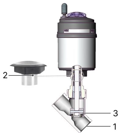
| Inspection Area | Check Item | Corrective Action |
|---|---|---|
| 1: Media Connections | External leakage at body joint or pipe ends | Retighten connection or re-weld / replace body gasket |
| 2: Relief Bore | Process medium weeping from relief weep hole | Stem packing gland is worn; replace packing set or actuator |
| 3: Swivel Plate / Seat | Internal cross-seat leakage | Replace swivel plate and PTFE seat seal kit |
For servicing the self-adjusting packing gland, use the authorized Bürkert installation socket wrench:
| Symptom | Probable Cause | Corrective Procedure |
|---|---|---|
| Actuator fails to switch | Control air connected to incorrect port | Connect pilot air to port 1 for CFA single-acting operation |
| Pilot pressure below 5.0 bar | Increase pilot air pressure to within 5.0 to 7.0 bar(g) range | |
| Operating medium pressure exceeds rating | Reduce system line pressure to below 25 bar(g) (20 bar for gas 1) | |
| Reversed line flow direction | Verify flow enters below seat according to body arrow marking | |
| Seat leakage in closed position | Foreign debris lodged on valve seat | Flush pipeline; install upstream dirt strainer (mesh < 1 mm) |
| Worn or scored PTFE seat seal | Install replacement swivel plate assembly | |
| Inadequate spring force / low pilot air release | Ensure pilot port vents completely to 0 bar(g) atmospheric pressure | |
| Fluid escaping from relief bore | Packing gland V-rings worn or degraded | Replace packing gland seal cartridge using tool 683221 |
Explore similar products in our catalog



