Transit-Time Ultrasonic

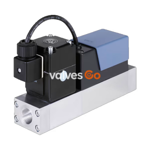
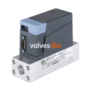
Burkert 556360 (Type 8012) continuous flowmeter with magnetic paddle wheel. Features 4-20 mA & transistor outputs, PVDF sensor, and G1 connection for 689-22,963 l/h flow rates.
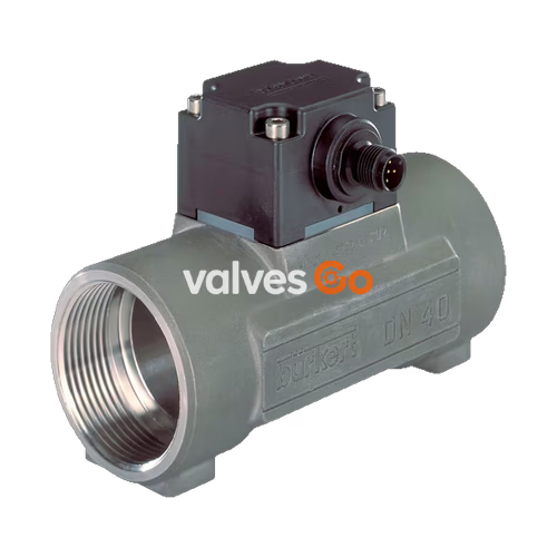
Burkert 556360 (Type 8012) is a continuous flowmeter equipped with a magnetic paddle wheel, designed for cost-effective integration into pipe systems without requiring additional pipelines. This specific model features a G1 connection, a PVDF paddle wheel, and supports flow rates from 689 to 22,963 l/h. It provides both a 4...20 mA analogue output and a transistor output, making it highly versatile for various industrial flow measurement applications involving neutral or mildly aggressive, particle-free liquids.
The Type 8012 family consists of a fitting (Type S012) and an electronic module (Type SE12) that are screwed together. Bürkert’s proprietary fitting system ensures simple installation into all pipelines from DN 06 to DN 65. The outputs are configurable via a USB port using a PC, allowing for customized frequency proportional to the volume flow rate or switching output modes.
The device Type 8012 is made up of a fitting Type S012 and a transmitter Type SE12 equipped with a paddle wheel sensor. The sensor detects the rotation of the paddle-wheel and generates a signal in which the frequency is proportional to the rotation frequency.
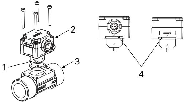
1: Paddle-wheel | 2: SE12 | 3: S012 | 4: Location of the LEDs
The electronic module is fitted with 2 LEDs visible by transparency on the side of the housing:
Make sure the device materials are compatible with the fluid you are using.
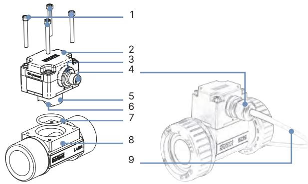
| No. | Element | Material |
|---|---|---|
| 1 | Screws | Stainless steel A4 |
| 2 | Housing | PPS |
| 3 | Seal | EPDM |
| 4 | M12 male connector or cable gland | PA |
| 5 | Axis and bearing | Ceramics ($Al_2O_3$) |
| 6 | Paddle wheel and holder | PVDF |
| 7 | Seal | FKM (EPDM as option) |
| 8 | Fitting body | Brass, stainless steel 1.4404/316L, PVC or PP |
| 9 | Cable | PVC |
| Property | Value |
|---|---|
| Measuring range | Flow rate: 0.5...1000 l/min (0.13...265 gpm) Flow velocity: 0.3...10 m/s |
| Measurement deviation | Teach-in: ± 1% of the measured value Standard K factor: ± 2.5% of the measured value |
| Linearity | ± 0.5% of full scale |
| Repeatability | ± 0.4% of the measured value |
| Viscosity | Max. 300 cSt (300 cP) |
| Rate of solid particles | Max. 1% (Maximum particle size: 0.5 mm) |
WARNING
Take the fluid pressure / temperature dependency into account according to the nature of the material of the fitting used.
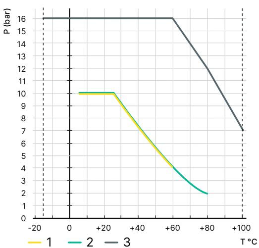 1: PVC | 2: PP | 3: Metal
| Property | Value |
|---|---|
| Operating voltage | 12...36 V DC ± 10%, filtered and regulated |
| Current consumption | <60 mA (at 12 V DC for current variant, without load) |
| Output | Transistor: NPN (default) or PNP, open collector, 700 mA max. Current: 4...20 mA (3 wire), sinking (default), loop impedance max.: 1125 Ω at 36 V DC |
| DC reverse polarity protection | Yes |
| Overvoltage protection | Yes |
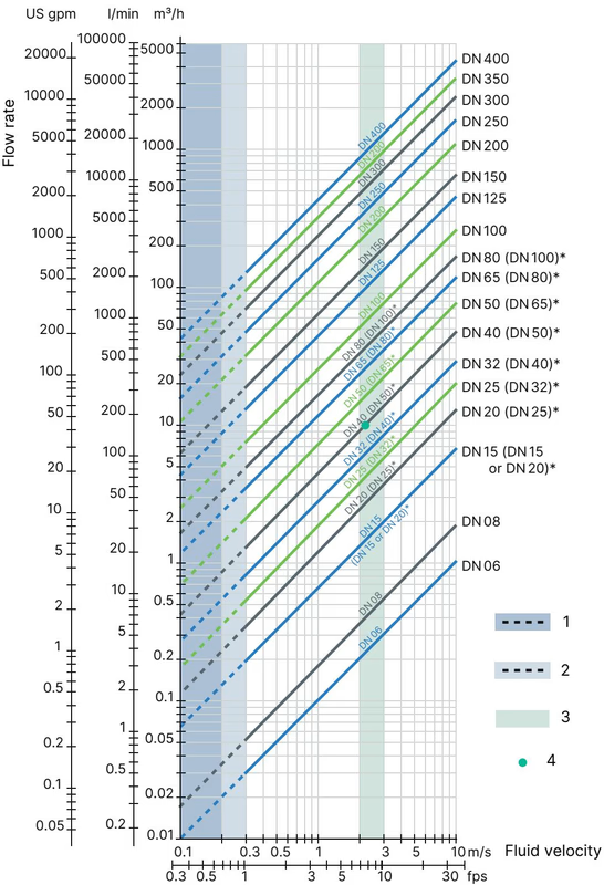
The following graph is used to determine the appropriate DN of the pipe and fitting for the application, according to the fluid velocity and the flow rate. On the chart, the intersection of flow velocity and flow rate gives the appropriate diameter.
INFO
The device is not suitable for use in gaseous media and steam.
Minimum straight distances upstream and downstream of the sensor must be observed. These stabilizing distances depend on the pipe’s design. Increasing these distances or installing a flow conditioner may be necessary to obtain the best accuracy (refer to EN ISO 5167-1).
The device can be installed in either horizontal or vertical pipes, but the following additional conditions must be respected:
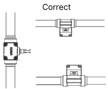 The paddle-wheel axis must be horizontal (Left: Correct, Right: Not correct)
 Ensure the pipe is always filled and prevent air bubbles (Left: Correct, Right: Not correct)
DANGER
Danger due to electrical voltage. Shut down and isolate the electrical power source before carrying out work on the system. Observe all applicable accident protection and safety regulations for electrical equipment.
Make sure the installation is equipotential. Connect the negative power supply terminal to the earth to eradicate the effects of common mode currents. If this connection cannot be made directly, a 100 nF / 50 V capacitor can be fitted between the negative power supply terminal and the earth.
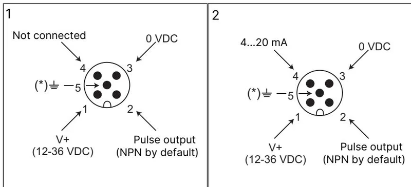 1: Version with pulse output | 2: Version with pulse and current output
| Pin | Colour of the wire (accessory cable) |
|---|---|
| 1 | brown |
| 2 | white |
| 3 | blue |
| 4 | black |
| 5 | grey |
Problems signalled by the LEDs:
| Status red LED | Status green LED | Status current output | Possible cause | Recommended action |
|---|---|---|---|---|
| Flashes 3 times every second | Off | 22 mA | Full scale exceeded (flow rate in the pipe is too high) | Check the process parameters |
| On | Off | 22 mA | Memory problem | Switch the power supply off then on. If the error persists, contact your Bürkert retailer. |
| Off | Flashes twice every second | 22 mA | The device with optical detection is mounted in the wrong direction | Mount the device, ensuring that the arrow on the side of the housing indicates the direction of the fluid. |
Problems not signalled by the LEDs:
| Problem | Recommended action |
|---|---|
| The device does not function | Check the wiring. Check that the device is energized. |
| The pulse output does not work | Check whether the wiring is suitable for the output type, NPN or PNP. |
| The current output does not work | Check whether the wiring is suitable for the output type, source or sink. |
| The flow rate measurement is incorrect | Recalculate and change the setting of the K factor. |
Explore similar products in our catalog