PWM Control

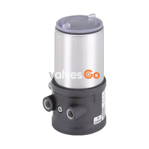
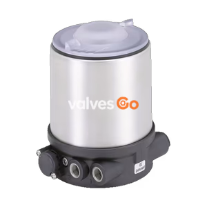
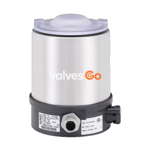
BURKERT 773140 (Type 1061) position feedback unit with electromechanical micro switches and integrated 5/2-way solenoid valve. Features optical position indicator and IP65 protection.
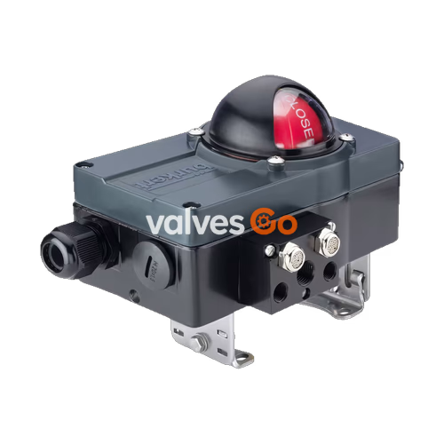
BURKERT 773140 (Type 1061) is a position feedback unit designed for pneumatic rotary actuators. It combines the functions of a position feedback indicator and a solenoid valve in a single compact box. This specific model features electromechanical feedback via micro switches and an integrated 5/2-way solenoid valve. It is perfectly suited for pneumatic rotary actuators such as Type 2051 and Type 2052. The mounting console with adjustable size enables use with actuators in different sizes, providing reliable on/off position feedback and actuator control.
| Property | Value |
|---|---|
| Housing Material | Aluminium |
| Seal Material | PUR |
| Base (powder-coated) | RAL9005 |
| Cover (powder-coated) | RAL7016 |
| Dome | Polycarbonate |
| Switching Precision | <1.5° |
| Bracket | Adjustable Hole gauge: 80/130 mm x 30 mm, Height: 20/30 mm |
| Degree of Protection | IP65 according to EN 60529 |
This model is configured with electromechanical feedback and a 5/2-way solenoid valve.
| Technical Data | Value |
|---|---|
| Limit Switch Manufacturer | Crouzet |
| Limit Switch Type | 83.161.301 micro switch |
| Switching Capacity | 4 A, 230 V AC/DC |
| Contacts | Silver nickel |
| System Connection | Cable gland M20 × 1.5 (Clamp range 8...13 mm) |
| Terminals | Screw-type terminals up to 2.5 mm² |
| Ambient Temperature | -10 °C...55 °C |
| Solenoid Valve Type | Type 6525 (Article no. 302828) |
| Ways | 5/2 |
| Operating Voltage | 24 V DC |
| Nominal Power | 0.8 W |
| Orifice | 4 mm |
| Supply/Exhaust Air | G 1/4, G 1/8 |
Dimensions in mm, unless otherwise stated.
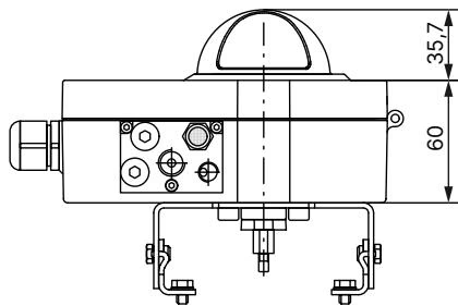
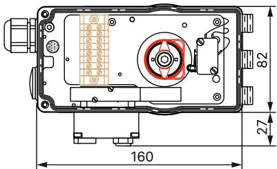
Risk of injury
The electric components inside the box carry dangerous voltage. Moreover there is a risk of bruise by some rotating parts. Do not open the housing while operating!

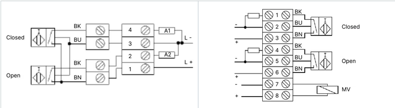
System connection with cable gland M20x1.5: Lead the system cable through the cable gland and wire the single conductors on the terminal block. Make sure that there is a sufficient mains lead cleat!
Ex factory the modules are adjusted in the following way:
If readjustment should be necessary proceed as following:
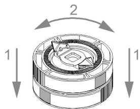
The limit-switch-box is equipped with an integrated 5/2-way solenoid valve. It is already wired on the terminal block, which means that the supply voltage comes via the system connection.
The pneumatic connection to the solenoid valve is realized by an external connection block. The types of connection are shown in the adjacent drawing.
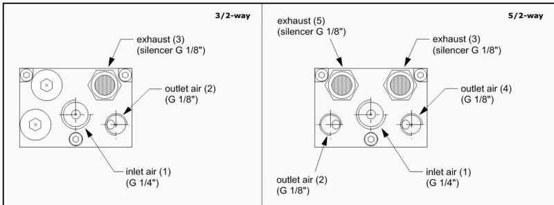
Long time outdoor usage can cause gaskets to become brittle after some time. Safe operation can only be guaranteed with leak-proof boxes. Seals should be checked and, if necessary, exchanged at least after five years. Gaskets may be replaced by qualified personnel only.
Explore similar products in our catalog