PN25
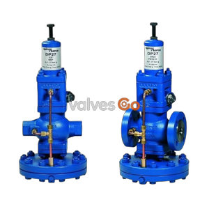
Spirax Sarco DP143 series pilot operated pressure reducing valves with cast steel bodies cover steam, compressed air, inert gas, high-temperature, and steriliser/autoclave service. Sizes range from DN15LC to DN80 with PN40, ANSI, and BS flange options, pressure ranges from 0.2 to 24 bar g by spring selection, and full materials, dimensions, capacities, and spare parts data.
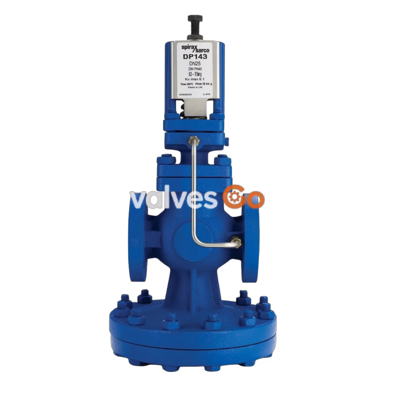
The Spirax Sarco DP143 series are pilot operated pressure reducing valves manufactured with cast steel bodies. The range covers four service variants: DP143 for steam, DP143G as a soft seal version for compressed air and inert industrial gases, DP143H for high-temperature operation up to 350 C, and DP143Y with a lower-rate pressure control spring for steriliser and autoclave applications.
This product fully complies with the requirements of the EU Pressure Equipment Directive 2014/68/EU and is available with EN 10204 3.1 certification when specified at the time of order placement.
| DP143 | Suitable for steam applications. |
| DP143G | Soft seal version for compressed air and inert industrial gases. Not recommended for oxygen service. |
| DP143H | High temperature version for use up to 350 C. |
| DP143Y | Low-rate pressure control spring version suitable for steriliser and autoclave applications. |
DN15LC low-capacity version, DN15, DN20, DN25, DN32, DN40, DN50, and DN80 are available.
Standard flanges: EN 1092 PN40, BS 10 Table J, and ANSI 300.
Available on request: ANSI 150 and JIS 20.
The Kv maximum values shown below are full capacities and should be used for safety valve sizing purposes only.
| DN15LC | DN15 | DN20 | DN25 | DN32 | DN40 | DN50 | DN80 |
| 1.0 | 2.8 | 5.5 | 8.1 | 12.0 | 17.0 | 28.0 | 64.0 |
For conversion: Cv (UK) = Kv x 0.963, Cv (US) = Kv x 1.156.
Where the internal balance pipe is used the valve capacity will be reduced.
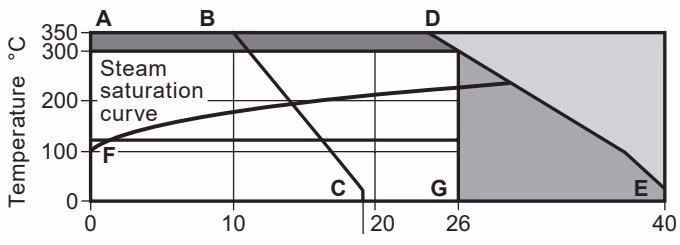
The product must not be used in the shaded region. Due to the material strength of the main diaphragm chamber, the product must not be used in that region. Use the high temperature DP143H version in the high-temperature region. A-D-E applies to flanged EN 1092 PN40, ANSI 300, and BS 10 Table J. A-B-C applies to flanged ANSI 150. F-G marks DP143G limited to 120 C at 26 bar g.
Two colour coded pressure adjustment springs are available for the following downstream pressure ranges:
| Red | 0.2 bar g to 17 bar g |
| Grey | 16.0 bar g to 24 bar g |
| Yellow | 0.2 bar g to 3.0 bar g (DP143Y only) |
| Condition | Variant / Connection | Value |
|---|---|---|
| Maximum design pressure | A-B-C | 18.9 bar g at 20 C |
| Maximum design pressure | A-D-E | Limited to 26 bar g |
| Maximum design temperature | All | 350 C at 24 bar g |
| Minimum design temperature | All | 0 C |
| Maximum upstream pressure for saturated steam service | A-D-E | 26 bar g |
| Maximum upstream pressure for saturated steam service | A-B-C | 14 bar g |
| Maximum operating temperature | DP143 | 300 C at 26 bar g |
| Maximum operating temperature | DP143G | 120 C at 26 bar g |
| Maximum operating temperature | DP143H | 350 C at 24 bar g |
| Minimum operating temperature | All | 0 C. For lower operating temperatures consult Spirax Sarco. |
| Maximum differential pressure | A-D-E | 26 bar |
| Maximum differential pressure | A-B-C | 14 bar |
| Maximum cold hydraulic test pressure | All | 60 bar g |
| Max test pressure with internals fitted | All | 40 bar g |
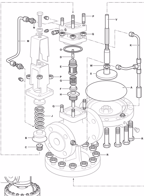
| No. | Part | Detail | Material / Grade |
|---|---|---|---|
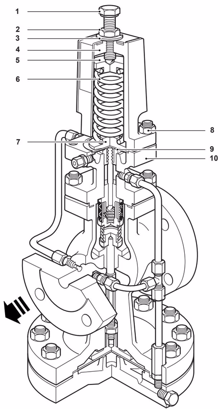
| 1 | Adjustment screw | Steel, BS 3692 Gr. 8.8 | |
| 2 | Adjustment lock-nut | Steel, BS 3692 Gr. 8 | |
| 3 | Washer | Stainless steel, BS 1449 304 S16 | |
| 4 | Spring housing | Cast steel, DIN 17245 GS C25 | |
| 5 | Top spring plate | Stainless steel, BS 970 220 Mo7 | |
| 6 | Pressure adjustment spring | Stainless steel, BS 2056 302 S25 | |
| 7 | Bottom spring plate | Stainless steel, EN 10088-3 1.4057 | |
| 8 | Spring housing securing set | Securing nuts | Steel, BS 3692 Gr. 8 |
| 8 | Spring housing securing set | Securing studs | Steel, BS 4439 Gr. 8.8 |
| 8 | Spring housing securing set | DN15 to DN80 | Stainless steel, M10 x 30 mm, BS 1449 316 S31 |
| 9 | Pilot diaphragm | Stainless steel, BS 1449 316 S31 | |
| 10 | Pilot valve housing | DN15 to DN50 | DIN 17245 GS C25 |
| 10 | Pilot valve housing | DN80 | GP 240 GH+N |
| No. | Part | Detail | Material / Grade |
|---|---|---|---|
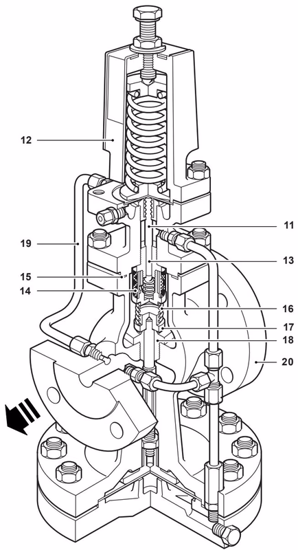
| 11 | Pilot valve plunger | Stainless steel, BS 970 431 S29 | |
| 12 | Spring housing cover | Stainless steel, BS 1449 304 S12 | |
| 13 | Pilot valve and seat unit | Standard | Stainless steel, BS 970 431 S29 |
| 13 | Pilot valve and seat unit | DP143G | Stainless steel / nitrile |
| 14 | Internal strainer | Stainless steel, BS 1449 304 S16 | |
| 15 | Body gasket | Stainless steel reinforced exfoliated graphite | |
| 16 | Main valve return spring | Stainless steel, BS 2056 302 S16 | |
| 17 | Main valve | Standard | Stainless steel, BS 970 431 S29 |
| 17 | Main valve | DP143G | Stainless steel / nitrile |
| 18 | Main valve seat | DP143G | Stainless steel / nitrile |
| 19 | Balance pipe assembly | Stainless steel, BS 3605 304 S14 | |
| 20 | Main valve body | Cast steel, DIN 17245 GS C25 |
| No. | Part | Detail | Material / Grade |
|---|---|---|---|
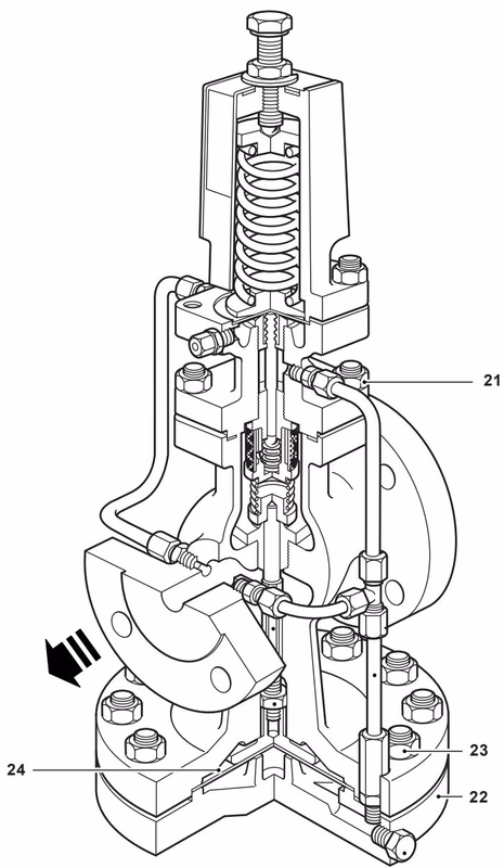
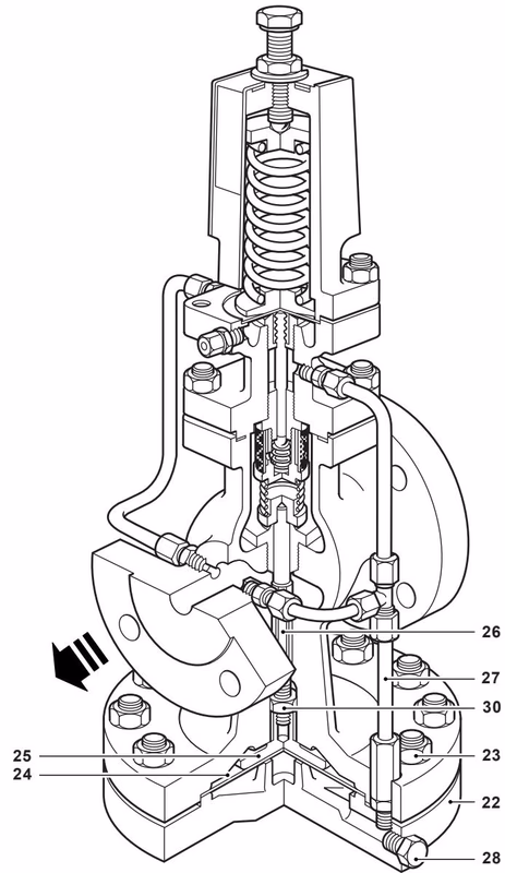
| 21 | Main diaphragm chamber securing set | Securing nuts | Steel, BS 3692 Gr. 8 |
| 21 | Main diaphragm chamber securing set | Securing studs | Steel, BS 4439 Gr. 8.8 |
| 21 | Main diaphragm chamber securing set | DN15 and DN20 | M10 x 25 mm |
| 21 | Main diaphragm chamber securing set | DN25 to DN50 | M12 x 30 mm |
| 21 | Main diaphragm chamber securing set | DN80 | M12 x 40 mm |
| 22 | Main diaphragm chamber | Cast steel, DIN 17245 GS C25 | |
| 23 | Main diaphragm securing set | Securing nuts | Steel, BS 3692 Gr. 8 |
| 23 | Main diaphragm securing set | DN15 and DN20 bolts | Steel, BS 3692 Gr. 8.8, M12 x 50 mm |
| 23 | Main diaphragm securing set | DN25 and DN32 bolts | M12 x 60 mm |
| 23 | Main diaphragm securing set | DN40 and DN50 bolts | M12 x 65 mm |
| 23 | Main diaphragm securing set | DN80 bolts | M12 x 80 mm |
| 24 | Main diaphragms | Stainless steel, BS 1449 316 S31 | |
| 25 | Main diaphragm plate | Stainless steel, BS EN 10088-3 1.4307 | |
| 26 | Push rod | Stainless steel, BS 970 431 S29 | |
| 27 | Control pipe assembly | Stainless steel, BS 3605 304 S14 | |
| 28 | Plug | 1/8 inch BSP | Steel |
| 29 | Pressure pipe union | Steel | |
| 30 | Lock-nut | Steel, BS 3692 Gr. 8 | |
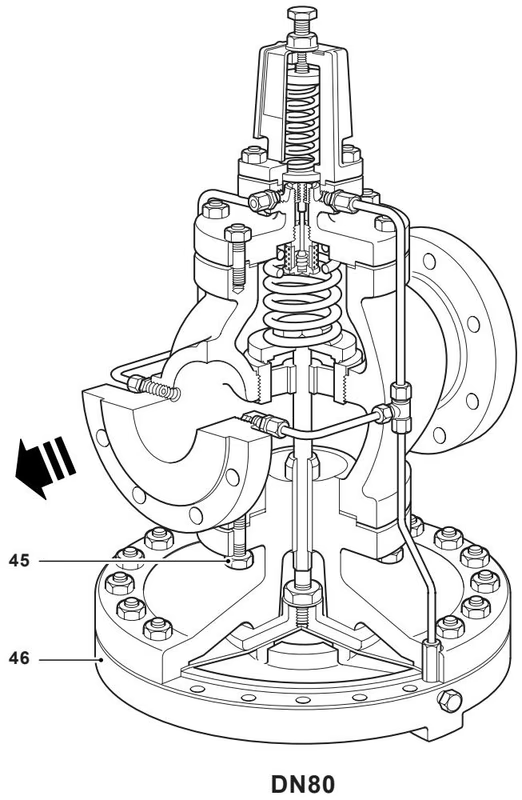
| 45 | Body studs | Steel, BS 4439 Gr. 8.8 | |
| 45 | Body nuts | Steel, BS 3692 Gr. 8 | |
| 45 | Body studs and nuts set | DN15 to DN80 | M12 x 40 mm |
| 46 | Upper main diaphragm chamber | Cast steel, 1.0619+N |
For DN80-specific parts, refer to the DN80 construction figure above.
| EN 1092 PN40 | ANSI300 | ANSI150 | BS 10 Table J | ||||||
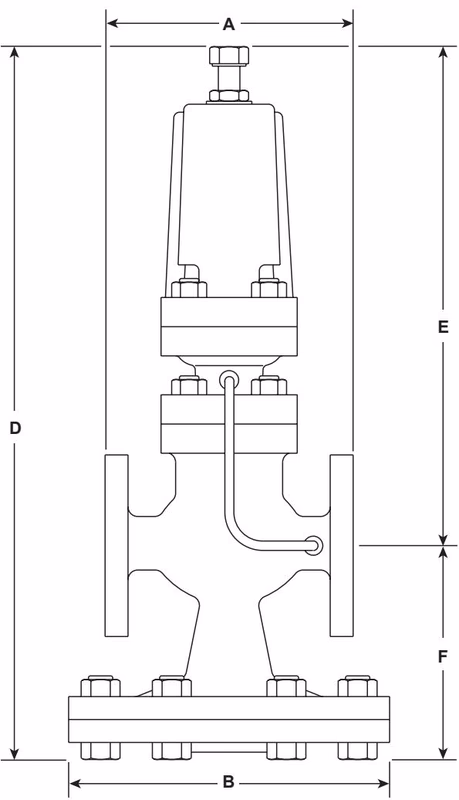
| Sizes | A | A | A | A | B | D | E | F | Weight kg |
| DN15 LC | 130 | 130 | 122 | 130 | 175 | 405 | 277 | 128 | 15 |
| DN15 | 130 | 130 | 122 | 130 | 175 | 405 | 277 | 128 | 15 |
| DN20 | 150 | 150 | 142 | 150 | 175 | 405 | 277 | 128 | 16 |
| DN25 | 160 | 160 | 156 | 164 | 216 | 440 | 288 | 152 | 23 |
| DN32 | 180 | 183 | 176 | 184 | 216 | 440 | 288 | 152 | 25 |
| DN40 | 200 | 209 | 200 | 209 | 280 | 490 | 305 | 185 | 40 |
| DN50 | 230 | 236 | 230 | 243 | 280 | 490 | 305 | 185 | 42 |
| DN80 | 310 | 319 | 310 | 325 | 350 | 580 | 322 | 258 | 103 |
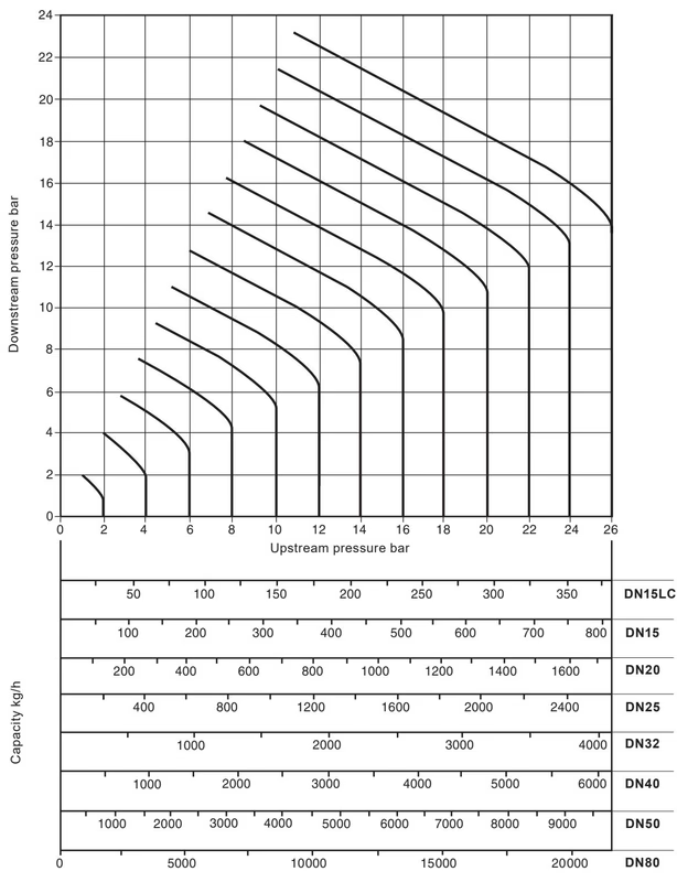
The capacities quoted above are based on valves fitted with an external pressure sensing pipe. Reliance on the internal balance pipe means capacities may be reduced. At low downstream pressure this reduction can be up to 30 percent of valve capacity.
How to use the chart for saturated steam: find the point at which the curved upstream pressure line crosses the horizontal downstream pressure line. A perpendicular dropped from this point gives the capacities of all DP sizes under those conditions. Example: for 600 kg/h reducing from 6 bar to 4 bar, DN32 is the smallest size that carries the required load.
For superheated steam, apply a correction factor to the chart value because of the higher specific volume. Use 0.95 for 55 C superheat and 0.9 for 100 C superheat. In the example above, a DN32 valve passes 740 x 0.95 = 703 kg/h at 55 C superheat, which still satisfies a 600 kg/h requirement.
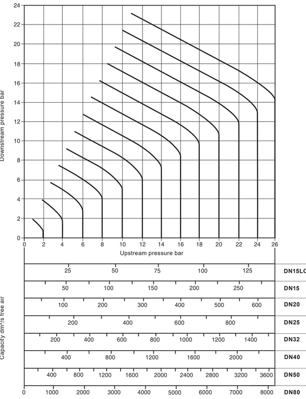
Capacities are given in cubic decimetres of free air per second, dm3/s. Example: to pass 100 dm3/s of free air reducing from 12 bar to 8 bar, find the intersection of the 12 bar upstream curve and the 8 bar downstream line. A DN15LC valve passes only about 57 dm3/s and is too small, while a DN15 valve passes approximately 120 dm3/s and is therefore the correct choice.
For full details see Installation and Maintenance Instructions IM-P006-07 supplied with the product.
Example: 1 off Spirax Sarco DN32 DP143 pilot operated pressure reducing valve fitted with a red pressure adjustment spring and having flanged EN 1092 PN40 connections.
| Maintenance kit: A stand-by set of spares for general maintenance purposes and covering all spares marked * | ||
| * Main diaphragm | (2 off) | A |
| * Pilot diaphragm | (2 off) | B |
| Pilot valve seal assembly | C | |
| * Pilot valve and plunger assembly | D, E | |
| Main valve assembly | F, H | |
| * Main valve return spring | G | |
| Pressure adjustment spring | Red, DP143 / DP143G / DP143H | J, 0.2 to 17 bar |
| Grey, DP143 / DP143G / DP143H | K, 16 to 24 bar | |
| Control pipe assembly | M | |
| Balance pipe assembly | N | |
| * Body gasket | (packet of 3) | O |
| * Set of spring housing securing studs and nuts | (set of 4) | P |
| * Set of pilot valve housing securing studs and nuts | (set of 4) | Q |
| Set of diaphragm chamber securing bolts and nuts | (set of 10) DN15 and DN20 | R |
| (set of 12) DN25 and DN32 | R | |
| (set of 16) DN40 and DN50 | R | |
| (set of 20) DN80 | R | |
| Set of main body studs and nuts (DN80) | (set of 6) | T |
| Pushrod and main diaphragm plate assembly | V, W, X | |
Always order spares by using the description given in the Available spares column and state the size and type of pressure reducing valve.
Example: 1 - Main valve assembly for a Spirax Sarco DN15 DP143 pressure reducing valve.
The following table shows how certain spare parts are interchangeable between sizes. In the line headed Main diaphragm, the diaphragm used in sizes DN15LC, DN15, and DN20 is common and marked by letter a. The letter b indicates DN25 and DN32 share another common diaphragm. Some parts, particularly pilot and main valve assemblies, are specific to particular models such as DP143G, so interchangeability may be limited by model type.
For storage purposes, the spare parts marked with the dagger note in the original literature are not the same material as those for the DP163 and may not be compatible for interchange. Parts marked with the double-asterisk note are not available for the DP143G.
| Size | DN15LC | DN15 | DN20 | DN25 | DN32 | DN40 | DN50 | DN80 |
| Main diaphragm | a | a | a | b | b | c | c | d |
| Pilot diaphragm | a | a | a | a | a | a | a | a |
| Pilot valve seal assembly | a | a | a | a | a | a | a | a |
| Pilot valve and plunger assembly | a | a | a | a | a | a | a | a |
| Main valve assembly | a | b | c | d | e | f | g | h |
| Main valve return spring | a | a | a | b | b | c | c | d |
| Pressure adjustment spring | a | a | a | a | a | a | a | a |
| Control pipe assembly | a | a | b | c | d | e | f | g |
| Balance pipe assembly | a | a | b | c | d | e | f | g |
| Body gasket | a | a | a | b | b | c | c | d |
| Set of spring housing securing studs and nuts | a | a | a | a | a | a | a | a |
| Set of pilot valve housing securing studs and nuts | a | a | a | b | b | c | c | d |
| Set of diaphragm chamber securing bolts and nuts | a | a | a | b | b | c | c | d |
| Set of main body studs and nuts | - | - | - | - | - | - | - | a |
Explore similar products in our catalog