Transit-Time Ultrasonic

The TLV EF200W-C Vortex Flowmeter provides accurate flow measurement for saturated steam, superheated steam, air, and water. Features IP66/67 protection and HART communication.
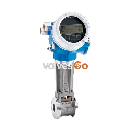
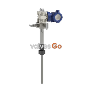
The TLV EF200W-C vortex flowmeter is designed to measure the flow of saturated steam, superheated steam, air, and water. Working on the principle of the Karman vortex phenomenon, it provides highly accurate volume and mass flow measurements. The device is available in two versions: a compact version where the transmitter and sensor form a single mechanical unit, and a remote version where they are mounted in separate locations.
Equipped with a robust IP66/67 (Type 4X) enclosure, the EF200W-C is built to withstand harsh industrial environments. It supports HART protocol communication and features a 4-line illuminated graphic display. The flowmeter is capable of handling fluid temperatures ranging from -200 to +400 °C (-328 to +752 °F) and is compliant with NACE MR0175 and MR0103 standards.
Prevent Mixed Phase and Excessive Flow
This flowmeter is designed to measure both gases and liquids. However, accurate measurement cannot be guaranteed when gases and liquids are mixed together (i.e., gas-liquid mixed phase flow). Additionally, excessive instantaneous or periodical flow rates should be held below the flow meter's maximum flow rate to prevent damage to the sensor, especially during steam startup.
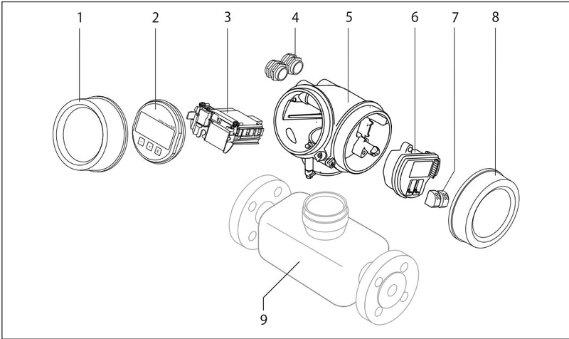
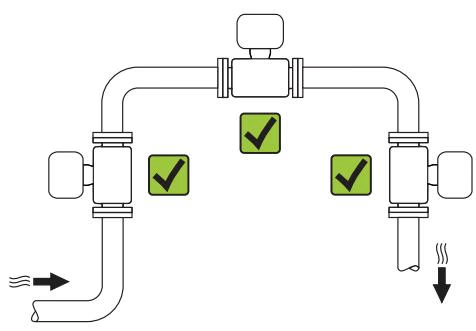
The direction of the arrow on the sensor nameplate helps you to install the sensor according to the flow direction. Vortex meters require a fully developed flow profile as a prerequisite for correct volume flow measurement.
| Orientation | Compact version | Remote version |
|---|---|---|
| Vertical orientation | Supported (Note 1) | Supported |
| Horizontal orientation, transmitter head up | Supported (Note 2, 3) | Supported |
| Horizontal orientation, transmitter head down | Supported (Note 4) | Supported |
| Horizontal orientation, transmitter head at side | Supported | Supported |
Note 1: In the case of liquids, there should be upward flow in vertical pipes to avoid partial pipe filling.Note 2: Danger of electronics overheating! If the fluid temperature is ≥ 200 °C (392 °F), this orientation is not recommended for compact versions.Note 3: In the case of hot media (e.g., steam ≥ 200 °C), use head down or head at side orientation.Note 4: In the case of very cold media (e.g., liquid nitrogen), use head up or head at side orientation.
To attain the specified level of accuracy, minimum inlet and outlet runs must be maintained depending on upstream flow obstructions.
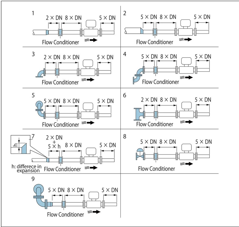
If the required inlet runs cannot be observed, it is recommended to install a specially designed flow conditioner. The flow conditioner is fitted between two pipe flanges and generally reduces the inlet run needed to 10 × DN or 13 × DN with full accuracy.
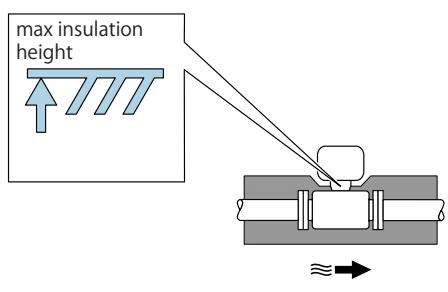
For optimum temperature measurement and mass calculation, heat transfer at the sensor must be avoided for some fluids. When insulating, ensure that a sufficiently large area of the housing support remains exposed to protect the electronics from overheating.
The following specified values are the largest possible flow measuring ranges for each nominal diameter. Depending on the fluid properties and environmental influences, the measuring range may be subject to additional restrictions.
| DN [mm] | Liquids [m³/h] | Gas/Steam [m³/h] |
|---|---|---|
| 15 | 0.06 to 4.9 | 0.3 to 25 |
| 25 | 0.18 to 15 | 0.9 to 130 |
| 40 | 0.45 to 37 | 2.3 to 310 |
| 50 | 0.75 to 62 | 3.8 to 820 |
| 80 | 1.7 to 140 | 8.5 to 1800 |
| 100 | 2.9 to 240 | 15 to 3200 |
| 150 | 6.7 to 540 | 33 to 7300 |
| Reynolds number range | Measured value deviation | Incompressible (Standard) | Compressible (Standard) |
|---|---|---|---|
| Re₁ to Re₂ | A2 | < 10 % | < 10 % |
| Re₂ to Re_max | A1 | < 0.75 % | < 1.0 % |
(Accuracy specifications valid up to 75 m/s)
Unit: kg/h
| Press. (MPaG) | Temp. (°C) | 15 mm (Min-Max) | 25 mm (Min-Max) | 50 mm (Min-Max) | 100 mm (Min-Max) |
|---|---|---|---|---|---|
| 0.1 | 120.4 | 5 - 40 | 14 - 183 | 52 - 689 | 190 - 2521 |
| 0.5 | 158.9 | 8.3 - 112 | 24 - 512 | 87 - 1927 | 317 - 7047 |
| 1.0 | 184.1 | 11 - 199 | 31 - 911 | 116 - 3424 | 423 - 12522 |
| 2.0 | 214.9 | 15 - 373 | 42 - 1702 | 158 - 6397 | 577 - 23391 |
| 3.0 | 235.7 | 18 - 549 | 51 - 2505 | 191 - 9413 | 700 - 34420 |
Explore similar products in our catalog