Cast Iron

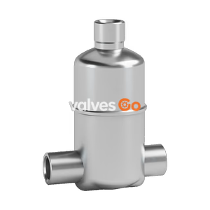
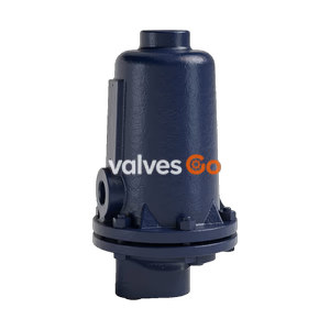
TLV JA3 and JAF3 free float air traps for compressed air systems. Features ductile cast iron body, 16 barg max operating pressure, and tight shut-off.
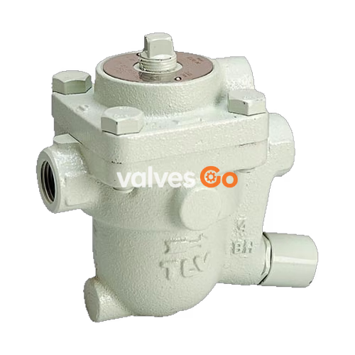
TLV JA3 and JAF3 are light free float air traps designed for pipe-end installation to automatically drain condensate and oil from compressed air systems. The JA3 features a screwed connection and ductile cast iron body, while the JAF3 features a flanged connection. Both models utilize a self-modulating free float that provides soft, continuous, and smooth, low-velocity discharge as process loads vary, ensuring a perfect air-tight seal even under low-load conditions.
| Model | JA3 | JAF3 |
|---|---|---|
| Connection | Screwed | Flanged |
| Size | DN 15 to DN 25 | DN 15 to DN 25 |
| Maximum Operating Pressure (PMO) | 16 barg | 16 barg |
| Maximum Differential Pressure (ΔPMO) | 16 bar | 16 bar |
| Maximum Operating Temperature (TMO) | 100 °C | 100 °C |
| Applicable Fluid | Air | Air |
WARNING
Local regulations may restrict the use of this product to below the conditions quoted. Do not use for toxic, flammable or otherwise hazardous fluids.
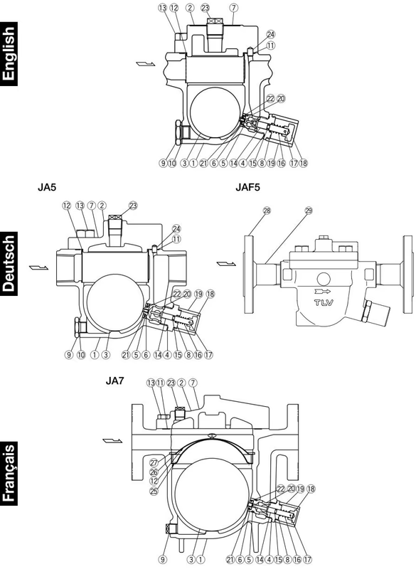
| No. | Description | Material | DIN | ASTM/AISI |
|---|---|---|---|---|
| 1 | Body (JA3) | Ductile Cast Iron GGG40.3 | 0.7043 | A395 Gr.60-40-18 |
| 1 | Body (JAF3) | Cast Iron | - | A842 Gr.400 |
| 2 | Cover | Ductile Cast Iron FCD450 | 0.7040 | A536 |
| 3 | Float | Stainless Steel SUS316L | 1.4404 | AISI316L |
| 4 | Holder Nut Gasket | Fluorine Resin PTFE | PTFE | PTFE |
| 5 | Valve Seat Holder O-Ring | Nitrile Rubber NBR | NBR | D2000BF |
| 6 | Valve Seat | Nitrile Rubber NBR | NBR | D2000BF |
| 8 | Valve Seat Holder Nut | Stainless Steel SUS420F | 1.4028 | AISI420F |
| 12 | Screen | Stainless Steel SUS430 | 1.4016 | AISI430 |
| 14 | Cleaning Needle | Stainless Steel SUS420F | 1.4028 | AISI420F |
| 18 | Plunger | Stainless Steel SUS420F | 1.4028 | AISI420F |
| 20 | Valve Seat Holder | Stainless Steel SUS420F | 1.4028 | AISI420F |
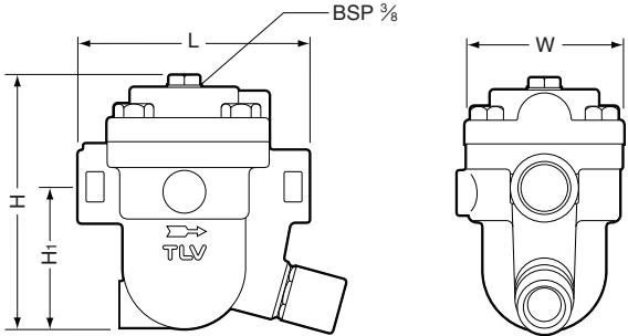
JA3 Screwed
| Size | L (mm) | H (mm) | H1 (mm) | W (mm) | Weight (kg) |
|---|---|---|---|---|---|
| 1/2" | 120 | 130 | 75 | 80 | 2.7 |
| 3/4" | 120 | 130 | 73 | 80 | 2.8 |
| 1" | 137 | 130 | 75 | 80 | 3.0 |
INFO
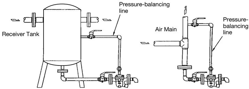
A pressure-balancing line must be connected to the air system from the balancing port at the top of the trap to a place above any possible condensate accumulation in the system.
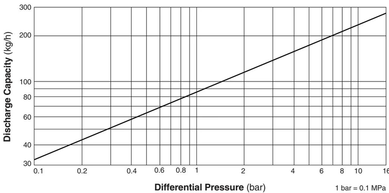
To ensure proper condensate flow into the trap, remove the balancing line plug and install a pressure-balancing line. Connect the end of the line to the air system at a place above any possible condensate accumulation.
A visual inspection can be done to help decide about necessary immediate maintenance or repair if the trap is open to atmosphere.
| Status | Description |
|---|---|
| Normal | Condensate is discharged continuously and the sound of flow like that of water draining from a bathtub can be heard. With very little condensate, there is almost no sound of flow. |
| Blocked | No condensate is discharged. The trap is quiet and makes no noise. The surface temperature of the trap is low. |
| Blowing | Air continually flows from the outlet and there is a continuous sound of a forceful stream against a surface. |
| Air Leakage | Air is discharged through the trap outlet together with the condensate and there is a hissing sound. |
If the trap shows signs of blockage, blowing or air leakage, perform manual blowdown by pushing the plunger in several times with a fingertip to allow dirt and oil to be discharged through the orifice.
Periodic operational inspections should be performed at least biannually or at intervals according to use. Faulty air traps may result in losses due to air leakage.
DANGER
NEVER apply direct heat to the float. The float may explode due to increased internal pressure, causing accidents leading to serious injury or property and equipment damage.
Parts Inspection Procedure:
| Problem | Cause | Remedy |
|---|---|---|
| No condensate is discharged (blocked) or discharge is poor | Float is damaged or filled with condensate | Replace the float |
| Orifice, screen or piping is clogged with rust, scale or dirt | Clean | |
| The trap operating pressure exceeds the maximum specified pressure, or there is insufficient differential pressure | Compare specifications and actual operating conditions | |
| Air binding occurs | Check and correct balance pipe and inlet pipe arrangement | |
| Air is discharged or leaks from the trap outlet (blowing) | Orifice is clogged or rust and scale have accumulated under the float | Clean |
| Orifice is damaged | Replace the orifice | |
| Float is deformed or coated with scale | Clean or replace the float | |
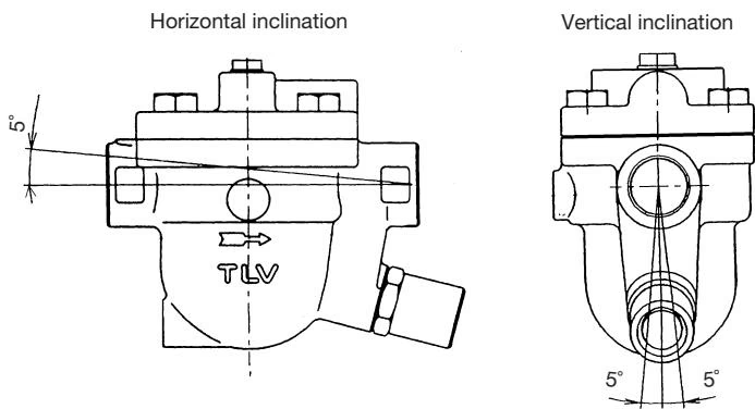
| Trap is installed above the maximum allowable inclination angle | Correct the installation |
Explore similar products in our catalog