Cast Iron

Armstrong 30 Series (32-LD, 33-LD, 36-LD) forged steel free floating lever drain traps feature elliptical floats and high leverage for capacities up to 19,050 kg/hr and pressures up to 69 bar.
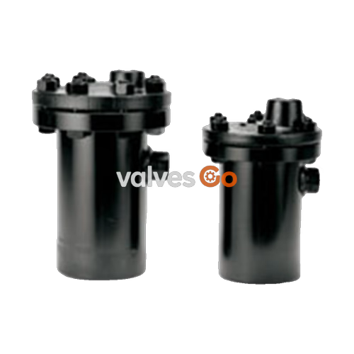
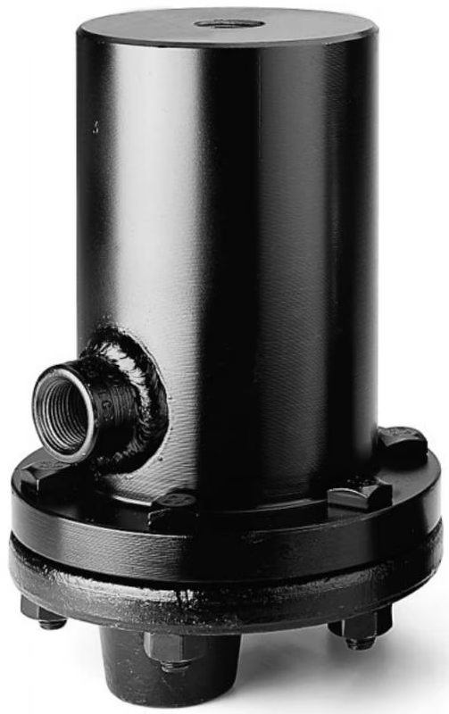
Armstrong 30 Series (32-LD, 33-LD, and 36-LD) forged steel free floating lever drain traps use the same highly reliable body, cap, leverage mechanism, valve, and seat as Armstrong inverted bucket steam traps. The elliptical floats and high leverage allow the drain traps to open large orifices, providing adequate capacity for the drainer's size and weight. The hemispherical valve, seat, and leverage of the 32-LD, 33-LD, and 36-LD stainless steel drain traps are identical in design, materials, and workmanship to those used in steam traps for pressures up to 69 bar (1,000 psig). Additionally, a guide pin is included to ensure a reliable, leak-tight seal under all conditions.
| Model | Valve & Seat | Leverage System | Float | Body & Cap | Gasket |
|---|---|---|---|---|---|
| 32-LD, 33-LD, 36-LD | Stainless Steel | Stainless Steel | Stainless Steel | Forged Steel ASTM A105 | Compressed Non-asbestos |
INFO
For special materials, please consult the factory. Socket weld or flanged connections are also available.
| Model | 32-LD | 33-LD | 36-LD |
|---|---|---|---|
| Pipe Size (DN) | 15, 20, 25 | 15, 20, 25 | 40, 50 |
| A (mm) | 171 | 203 | 302 |
| B (mm) | 259 | 294 | 435 |
| D (mm) | 141 | 154 | 229 |
| K (mm) | 32 | 37 | 54 |
| L (mm) | 86 | 90 | 154 |
| Weight (kg) | 14 | 22 | 74 |
| Max Allowable Pressure (Vessel Design) | 4.1 MPa @ 38°C 3.4 MPa @ 400°C | 6.9 MPa @ 38°C 4.1 MPa @ 400°C | 6.9 MPa @ 38°C 4.1 MPa @ 400°C |
Note: In some cases, the vessel design pressure may exceed the float's pressure rating. Vent connection size is the same as the inlet/outlet connection size. 316 stainless steel versions are available upon request.
Pipe Fitting: Before hooking up drainers, clean the pipes carefully after cutting and threading. To clear the pipes of dirt, pipe cuttings, and other foreign objects, blow-down the drainer connected to the system at full pressure.
Strainers are necessary if there is a chance that scale and sediment can be carried to the drainer. Shut-off valves and unions should be installed so the drainer can be examined and/or serviced without shutting down the unit being drained.
WARNING
Maximum operating pressure is stamped on the drainer. Do not exceed this pressure.
Operation Rules:
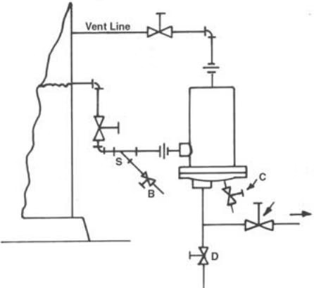 Figure 1. Installation of ball float drainer for medium or heavy loads. Strainer blow-down valve “B” and drainer blowdown valve “C” are optional.
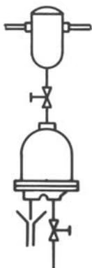 Figure 2. Installation of drainer when amount of liquid is small enough so liquid can flow to drainer countercurrent to gas displaced. Note: Drain line should be 3/4” minimum and kept as short as possible.
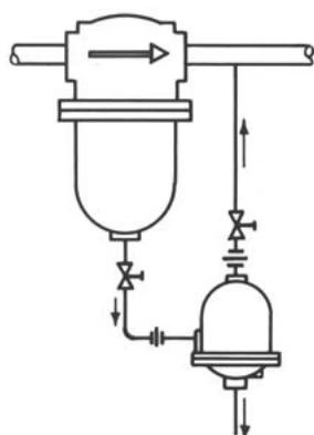 Figure 3. Installation of drainer for separator applications where back venting is necessary. Notice that the drainer is vented to the downstream side of the separator.
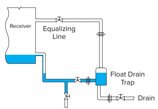
This is the best method for piping in a liquid drainer. The liquid drainer is below the receiver to allow the receiver to drain out completely, and the drainer is back vented. Notice there are no dips in the piping.
For light loads only: The drain trap installed at the side of a receiver, close to the floor. This piping method works because the liquid drainer is back vented. However, the liquid drainer is not below the receiver, so the receiver will hold a water level. Since the liquid drainer is back vented, the water seal does not cause any issues.
As long as the strainer is regularly blown down: Installation with a strainer protecting the drain trap. A strainer can be used when a dirt pocket is absent as long as there is a regular blowdown schedule to clean the strainer screen.
A regular schedule should be set up for drainer testing and preventative maintenance. Drainer size and operating pressure determine how frequently drainers should be checked:
Make sure that your parts are stamped with the orifice size required for your operating pressure. Parts with different orifice stampings should never be used together.
Armstrong valves and seats have been carefully lapped together and are furnished for installation as matched sets. Do not use a new seat with an old valve (or vice-versa). Pipe dope or lubricant is not required on valve seat threads. The joint is made by metal-to-metal contact at the ground end of the valve seat.
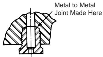 Important! Valve seat seal is made at the point of contact indicated, not by threads.
Fulcrums of levers are sheared at the factory to obtain maximum opening pressure as well as maximum valve travel which ensures full capacity. Never tamper with the height or position of fulcrums.
Pins always point away from the adjoining gasket surface.
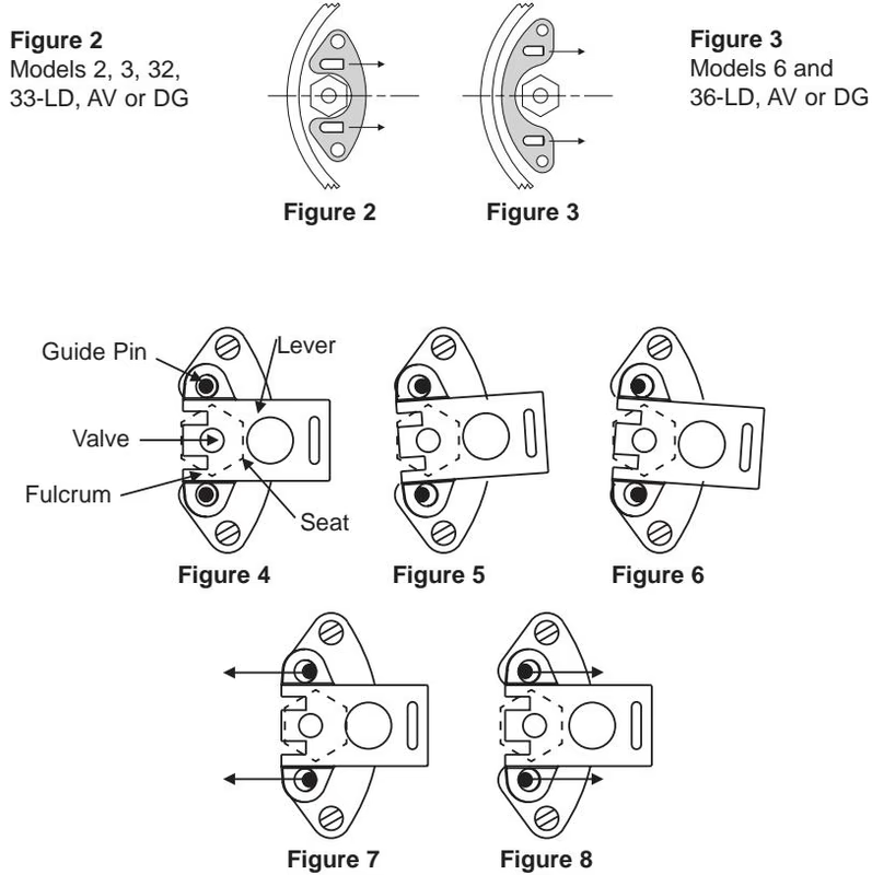
To check the alignment of guide pins, hold the lever and valve against the valve seat with the valve contacting its seat and the two fulcrum points resting on the face of the seat. When correctly aligned, the lever can be moved sideways the same distance to the right as to the left. Should the guide pins be out of line, they should be straightened so that they will be central in the guide pin holes.
Explore similar products in our catalog